Light condensing lens and three-dimensional distance measuring apparatus

a three-dimensional distance and light condensing technology, applied in the direction of fixed installation, lighting and heating equipment, instruments, etc., can solve the problems of plurality of wide-angle short-focus lenses, difficult to provide a light receiving element, and difficult to effectively condense light on the light receiving element, so as to increase the amount of laser light received and efficient laser light reception

Inactive Publication Date: 2013-08-29
SONY CORP
View PDF2 Cites 2 Cited by
  • Summary
  • Abstract
  • Description
  • Claims
  • Application Information

AI Technical Summary

Benefits of technology

[0018]In view of the foregoing, it is desirable to provide a light condensing lens and a three-dimensional distance measuring apparatus that secure a sufficient amount of light received by a light receiving element and that reduce the light receiving area of the light receiving element.
[0053]This allows efficient laser light reception, and increases the amount of received laser light.

Problems solved by technology

Even if a wide-angle short-focus lens is used, however, the numerical aperture of the lens is limited, and therefore the image height may be very large depending on the magnitude of the view angle, which may make it difficult to effectively condense light on the light receiving element.
Because the wide-angle short-focus lenses have a large numerical aperture, however, it may be difficult to provide a light receiving element that is common among the plurality of wide-angle short-focus lenses.

Method used


Image

  • Light condensing lens and three-dimensional distance measuring apparatus
  • Light condensing lens and three-dimensional distance measuring apparatus
  • Light condensing lens and three-dimensional distance measuring apparatus

Examples


first embodiment

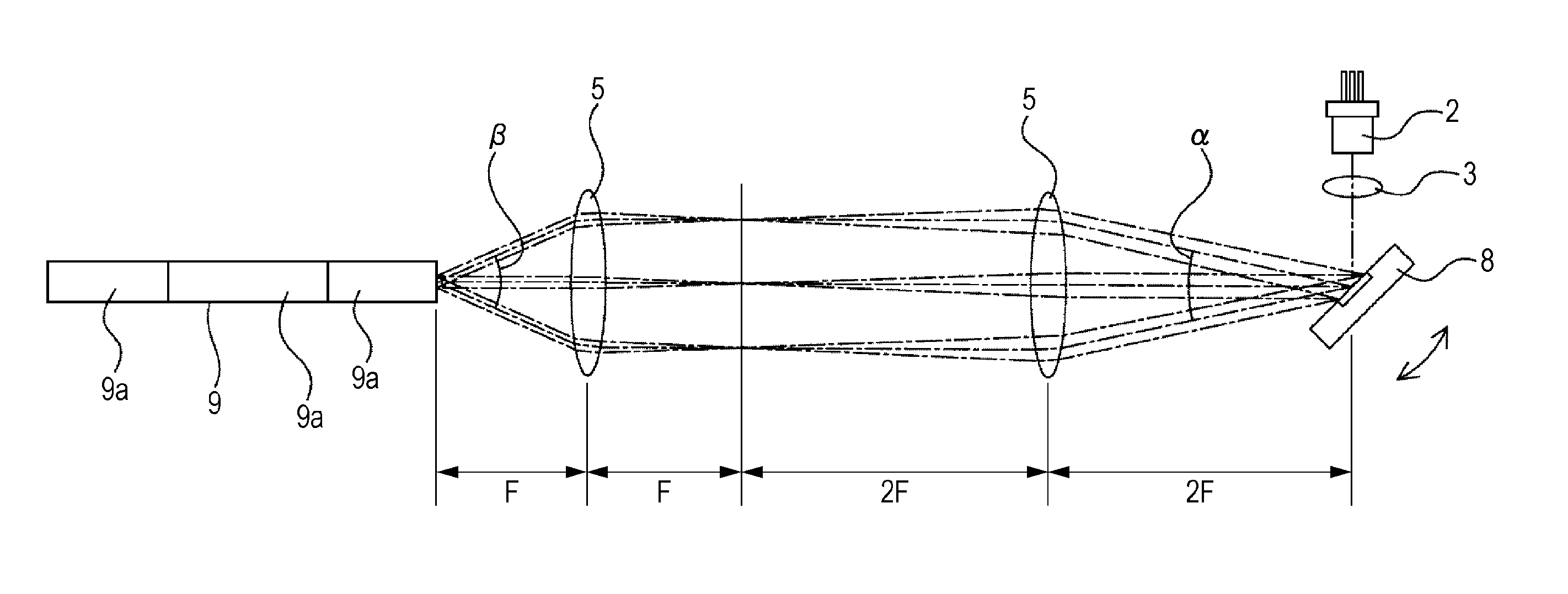
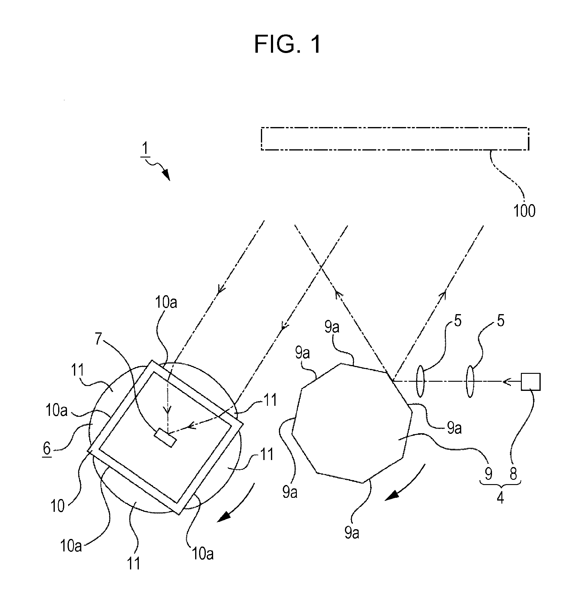
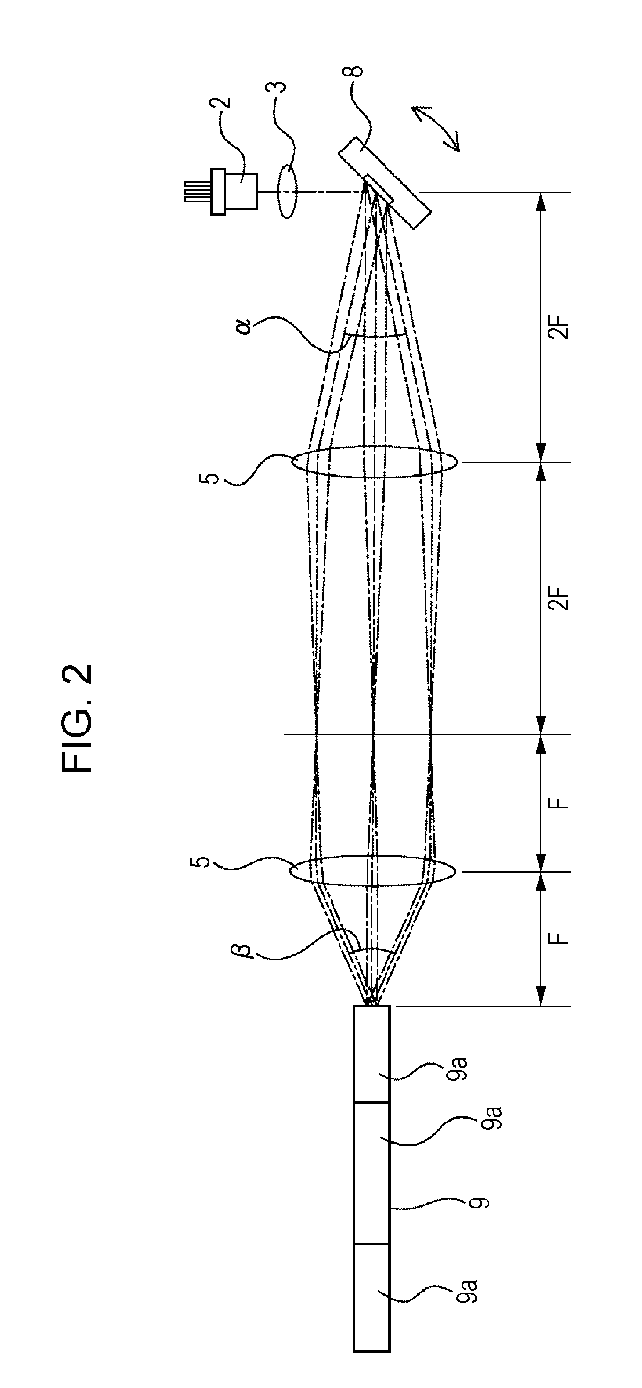
[0075]First, a three-dimensional distance measuring apparatus 1 according to a first embodiment will be described with reference to FIGS. 1 to 3.

[0076]The three-dimensional distance measuring apparatus 1 includes a laser light source 2, an optical element 3, a light projecting mirror 4, a relay lenses 5, 5, a light condensing unit 6, and a light receiving element 7 (see FIGS. 1 to 3).

[0077]The laser light source 2 may be a laser diode, for example. The laser light source 2 may oscillate laser light with various wavelengths depending on the constituent element of a semiconductor. A plurality of laser light sources 2 may be provided.

[0078]The optical element 3 may be a collimator lens, for example. The optical element 3 has a function of shaping incident laser light into generally parallel light to emit the generally parallel light.

[0079]The light projecting mirror 4 includes a first reflecting mirror 8 and a second reflecting mirror 9.

[0080]The first reflecting mirror 8 may be a MEMS...


PUM


Abstract

A light directing system including first and second relay lenses through which light passes, the first and second relay lenses being positioned at conjugate positions, the first relay lens being positioned between the second relay lens and a light source, a focal length of the first relay lens being longer than a focal length of the second relay lens.

Description

RELATED APPLICATION DATA[0001]This application is a continuation of U.S. patent application Ser. No. 12 / 917,006 filed Nov. 1, 2010, the entirety of which is incorporated herein by reference to the extent permitted by law. The present application claims the benefit of priority to Japanese Patent Application No. JP 2009-256053 filed on Nov. 9, 2009 in the Japan Patent Office, the entirety of which is incorporated by reference herein to the extent permitted by law.BACKGROUND OF THE INVENTION[0002]1. Field of the Invention[0003]The present invention relates to the technical field of light condensing lenses and three-dimensional distance measuring apparatuses. More particularly, the present invention relates to the technical field of light condensing lenses for condensing laser light on a light receiving element including a plurality of lenses disposed side by side in a splitting direction of a view angle to secure a sufficient amount of light received by the light receiving element and ...

Claims


Application Information

Patent Timeline
Patent Type & Authority Applications(United States)
IPC IPC(8): F21V13/04F21V13/06G01S17/10
CPCG01S7/4811G01S7/4817G01S17/10F21V13/06G02B3/02G02B27/123F21V13/04G01S17/42
Inventor KANEDA, KAZUMASAASOMA, YOSHITO
Owner SONY CORP
Why Eureka
Try Eureka