Insulating Member for Building Construction

a technology for building construction and insulation parts, applied in the direction of roofs, building components, roof coverings, etc., can solve the problems of insufficient amount of insulation, inefficiency in heating or cooling the building, and difficulty in controlling the application of insulation (depth, evenness, etc.) to achieve the effect of air flow

Active Publication Date: 2013-09-05
PETERSON JOSEPH
View PDF2 Cites 7 Cited by
  • Summary
  • Abstract
  • Description
  • Claims
  • Application Information

AI Technical Summary

Benefits of technology

[0019]The present invention is an insulating member which is formed as a singular structure, preferably comprised of a non-compressible polymer. The insulating member includes a first surface for contacting the top plate of the wall of the building; a second surface for overlaying the outer surface of the wall; and the third surface shaped to conform with, and to be evenly spaced from the underside of the associated roof, adjacent to the top plate of the wall, to create a uniform air gap between the insulating member and the underside of the roof. The insulating member is preferably dimensioned to provide at least three inches of insulating material for surrounding the top plate of the wall, achieving a significant improvement in insulation R value.
[0020]The present invention may be described as a polygonal insulating member for sealing off the opening between a soffit space and an attic space in a building structure. The insulating member is comprised of a base rectangular portion having bottom planar surface for contacting and overlying the attic side of a room ceiling and the top plate of an exterior side wall of said structure and opposite side planar surfaces for contacting and fitting between adjacent room ceiling joists and adjacent roof rafters and an extension rectangular portion having an inner planar surface for contacting and overlying the exterior surface of the exterior wall extending downward a predetermined distance extending past the top plate of said exterior side wall. The contiguous insulating member also includes an upper triangular portion coterminous with and directly atop the base rectangular portion for contacting and underlying the roofing panels and opposite side planar surface for contacting and fitting between adjacent roof rafters. In order to provide for air flow between the soffit space and the attic space a first air flow channel is formed into the top surface of the upper triangular portion with the roof panels completing the fourth side of the air flow channel. A second air flow channel extends through the base rectangular and upper triangular portion in parallel to said first air flow channel. Both of the first and second air flow channels provide air flow from the soffit space to the attic space such that the polygonal insulating member provides an increased insulating factor between the soffit space and the attic space while permitting air flow therebetween to reduce moisture retention and staunch the growth of mold and mildew in the soffit and attic spaces.

Problems solved by technology

Loose-fill insulation has the disadvantage that it is often difficult to control the application (depth, evenness, etc.) of the insulation, and it is not unusual for such insulation to clog ventilation conduits or other structures located within the walls or beneath the roof.
Further, when such insulation is either blown (for loose-fill) or rolled (for loose bales) into the wedge-shaped recess which is typically defined at the edges of an attic space, between the attic floor and the underside of the inclined roof, an insufficient amount of insulation is often achieved, developing a significant “cold spot” at the intersection between the top plate of the wall, the edge of the ceiling, and the roof.
Spray foam requires the blocking off of areas that require air flow and are not considered to be appropriate for the junction of the three building structure components.
The presence of a “cold spot,” or area of relatively little insulation, will generally cause inefficiency in heating or cooling of the building.
Typically, a ceiling is insulated (with an appropriate insulating material) to an insulation value of “R30”, while a wall is typically insulated to an insulation value of “R19.” However, at the intersection of the ceiling and roof, there will be a deficiency of insulation material (at the “cold spot”), decreasing the insulation value of the overall construction.
What is more, it has been observed that the “cold spot” formed at the intersection of the wall, ceiling and roof tends to cause condensation of moisture, which can lead to the formation of mold and mildew on the inside of the adjacent wall or the underside of the roof decking material without continuing airflow through the area.
Over a long period of time, such mold or mildew may contribute to structural decay.
Grange specifically lacks any substantial amount of insulating material that engages along the top plate of the vertical structural wall and extends any length downward along the exterior of the wall to afford sufficient insulating material in this critical are of the structure.
There is lacking any description of extending any insulation downward along the wall exterior in the soffit space to enhance the insulating factor of the device.
Further, the structure does not appear sufficiently rigid and can be deformed along its upper side by insulation batts thereby reducing the air channel and the air flow from the soffit area to the attic space.
However, again there is not even a suggestion of extending the insulation outward and downward along the exterior of the wall, ceiling and roof intersection to provide for an enhanced insulation factor at the junction.
While improving the insulation value developed at the intersection of an exterior wall, uppermost room ceiling and roof of a building, the above devices fail in any way to completely insulate the junction of the three structural elements of the building.
In addition to compromising the insulation value for the wall, the proximity of the “cold” space atop the wall tends to promote the formation of mold and mildew, as previously described.

Method used


Image

  • Insulating Member for Building Construction
  • Insulating Member for Building Construction
  • Insulating Member for Building Construction

Examples


Embodiment Construction

[0029]The following detailed description is of the best presently contemplated mode of carrying out the invention. The description is not intended in a limiting sense, and is made solely for the purpose of illustrating the general principles of the invention. The various features and advantages of the present invention may be more readily understood with reference to the following detailed description taken in conjunction with the accompanying drawings.

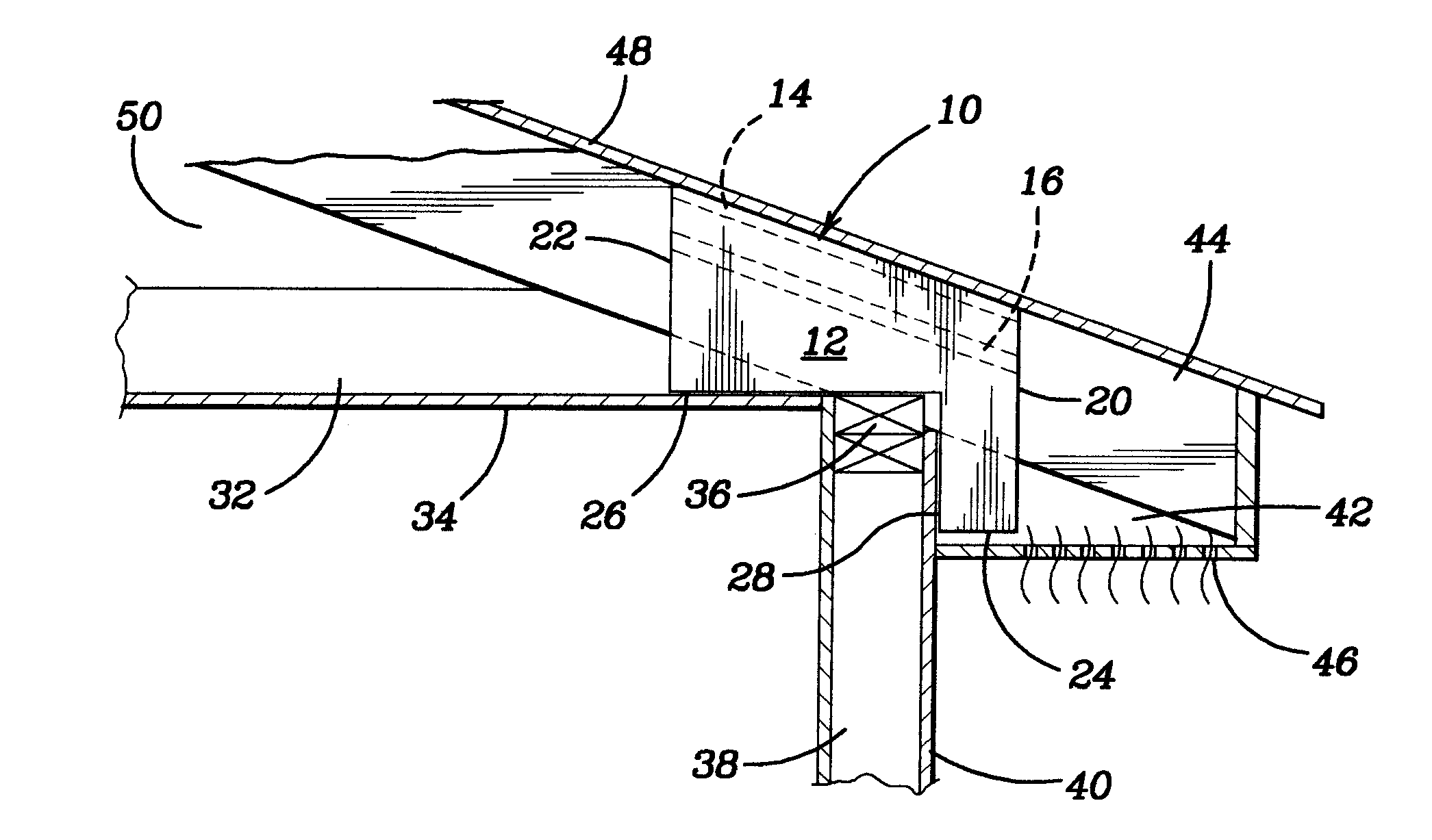
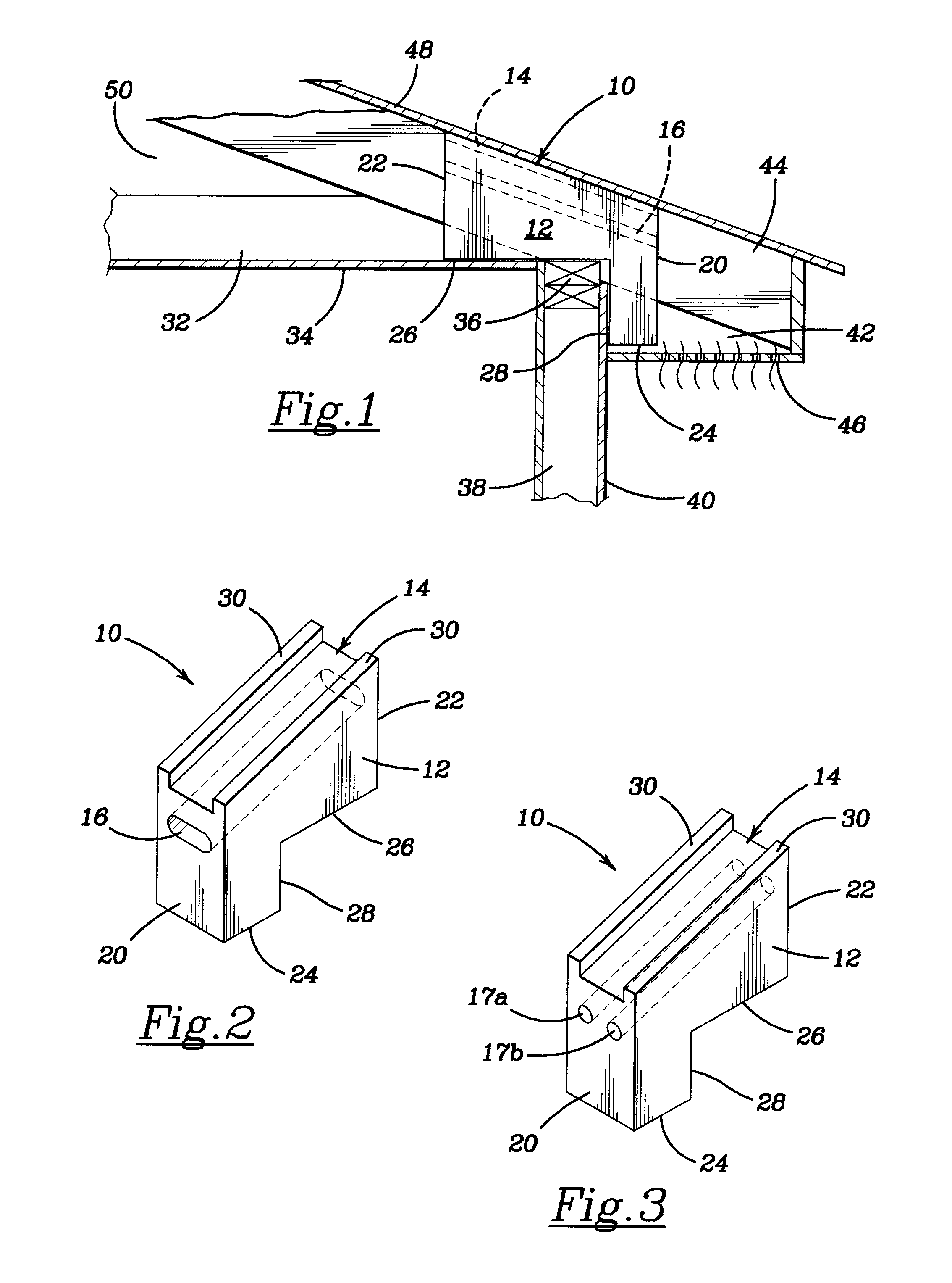
[0030]Referring now to the drawings in detail, where like numerals refer to like parts or elements, there is shown in FIG. 2 a typical insulating member 10 produced in accordance with the present invention. The insulating member 10 is formed as a solid body 12 which is preferably made of a closed-cell substantially non-compressible foam, of a type conventionally used in insulating materials. The solid body 12 may be covered with a thin plastic film (not shown) to prevent damage in shipping and installation. The insulating member 10 is...


PUM

PropertyMeasurementUnit
depthaaaaaaaaaa
depthaaaaaaaaaa
depthaaaaaaaaaa

Abstract

An insulating member is disposed between the top of a wall and the underside of a roof to more effectively insulate the structure and prevent condensation fostering growth of mold and mildew occurring along the surfaces of the wall, ceiling and roof. A first surface of the insulating member overlies the top plate of the wall extending inward between the ceiling joists a distance of at least 1.5 feet. A second surface overlies the outside surface of the wall extending downward along the exterior of the wall a distance of at least 0.5 feet. A third surface is shaped to substantially conform to the opposing underside of the roof deck such that the space between the roof deck and the wall top plate is sealed off by the insulating member. Multiple air flow pathways extend through the insulating member providing continuous air flow from soffit area into the attic space.

Description

BACKGROUND OF THE INVENTION[0001]The present invention generally relates to an insulating member for use in the construction of buildings, and more particularly, to an insulating member to be disposed between the upper top plate of a wall and the underside of the roof decking of the roof of a building.[0002]The effective thermal insulation of buildings, both residential and commercial, has become a crucial concern for builders and homeowners as the cost of heating and cooling has increased and the desire to reduce one's carbon footprint and go “green.” For this reason, in addition to the basic thermal insulation properties of ordinary wood and masonry, it has become common practice to employ various types of insulating material, such as fiberglass mats or expanding foams, in both new and existing buildings. Such insulating material may typically be installed in loose bales which are spread over the floor of an attic or be sprayed between the studs of a wall. Alternatively, such insu...

Claims


Application Information

Patent Timeline
Patent Type & Authority Applications(United States)
IPC IPC(8): E04B1/70E04C2/20E04B1/92
CPCE04D13/172E04D13/155E04D13/152E04D13/178
Inventor PETERSON, JOSEPH
Owner PETERSON JOSEPH
Why Eureka
Try Eureka