Attachment clip for ceiling grid systems

a technology for ceiling grids and attachment clips, which is applied in the direction of building reinforcements, constructions, building components, etc., can solve the problems of affecting the appearance of the trim strip, etc., and achieves the effect of quick and easy positioning on the trim strip, no risk of damage to the trim strip, and avoiding the risk of strip damag

Active Publication Date: 2013-09-05
USG INTERIORS INC
View PDF41 Cites 49 Cited by
  • Summary
  • Abstract
  • Description
  • Claims
  • Application Information

AI Technical Summary

Benefits of technology

[0005]The invention provides an improved attachment clip for suspended ceiling perimeter trim that is quick and easy to position on a trim strip and that avoids the risk of damage to the strip in the event of over tightening.
[0006]The disclosed clip has a main body with divergent legs, one for attachment to the trim strip and the other for attachment to a grid runner. A backer plate is slidably mounted on the trim attachment leg between retracted and extended positions. The backer plate retracted position allows the clip to be installed from any point along the length of a trim strip rather than by sliding it from an end of the trim strip. The clip geometry permits the clip to hang, cantilever fashion, on the trim strip during initial assembly without deploying the backer plate into its extended locking position. Once a location of the clip on the trim strip has been selected, the backer plate can be extended to secure the clip on the trim strip.
[0007]The clip is locked in position on the trim strip by tightening a screw assembled through the trim attachment leg into the backer plate. Tightening of the screw pinches or clamps a part of a respective track channel on the rear side of the trim in which the backer plate is received. Since the clamping force is not directed against a mid-section of the trim strip, there is no risk of damaging the appearance of the trim strip. The clamping force of the screw is spread across relatively large flat areas of the trim so that permanent local deformation of the trim is avoided. Consequently, fine readjustment of the position of the clip is not obstructed by edges or bumps which could otherwise be created in the clamped trim area. The grid runner attachment leg incorporates a horizontal cut line that allows a technician to easily modify this leg to mate with different grid runner configurations.

Problems solved by technology

Prior art clips, when being installed, can cause distortion of the trim if overly tightened, and can be expensive to manufacture.

Method used


Image

  • Attachment clip for ceiling grid systems
  • Attachment clip for ceiling grid systems
  • Attachment clip for ceiling grid systems

Examples


Embodiment Construction

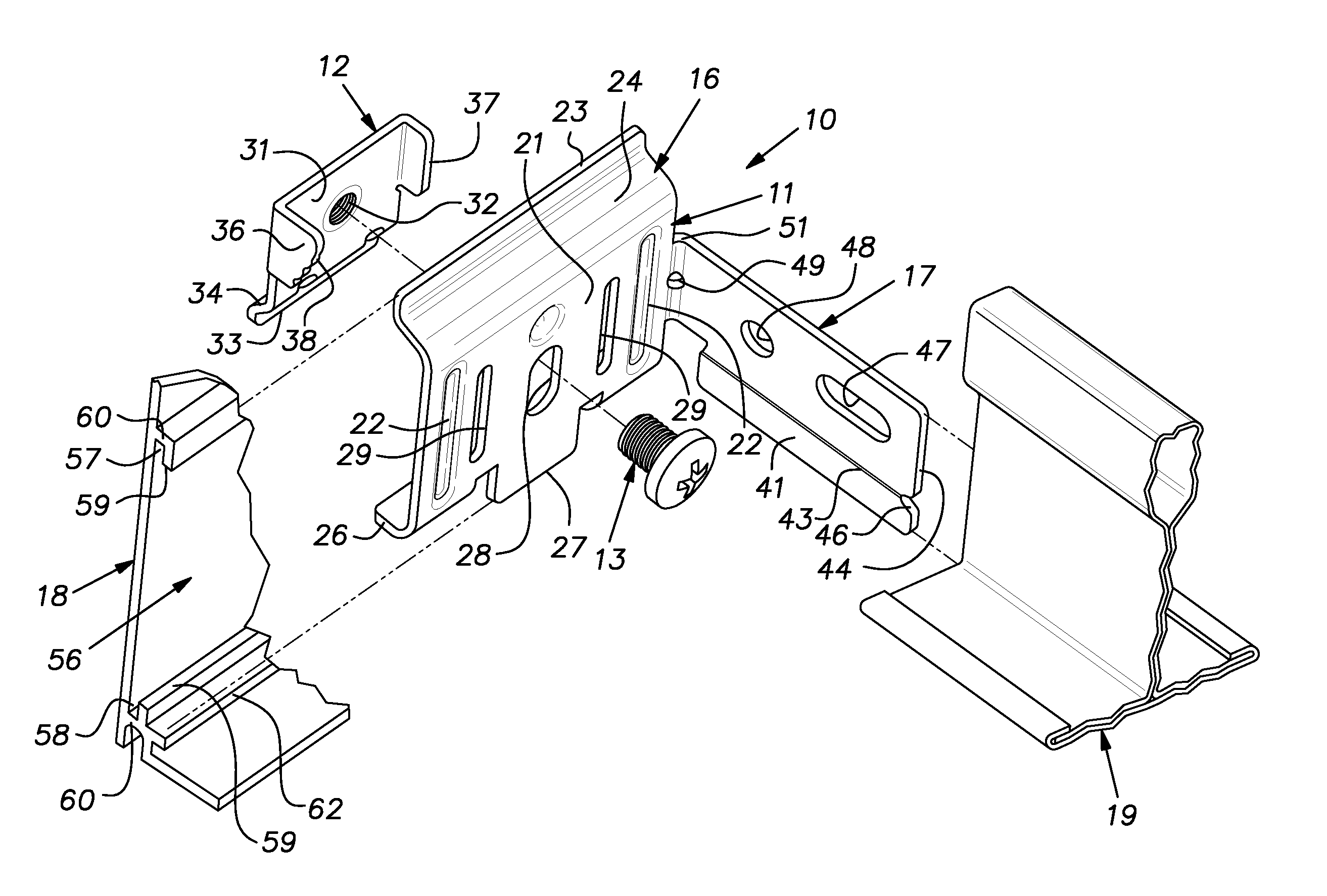
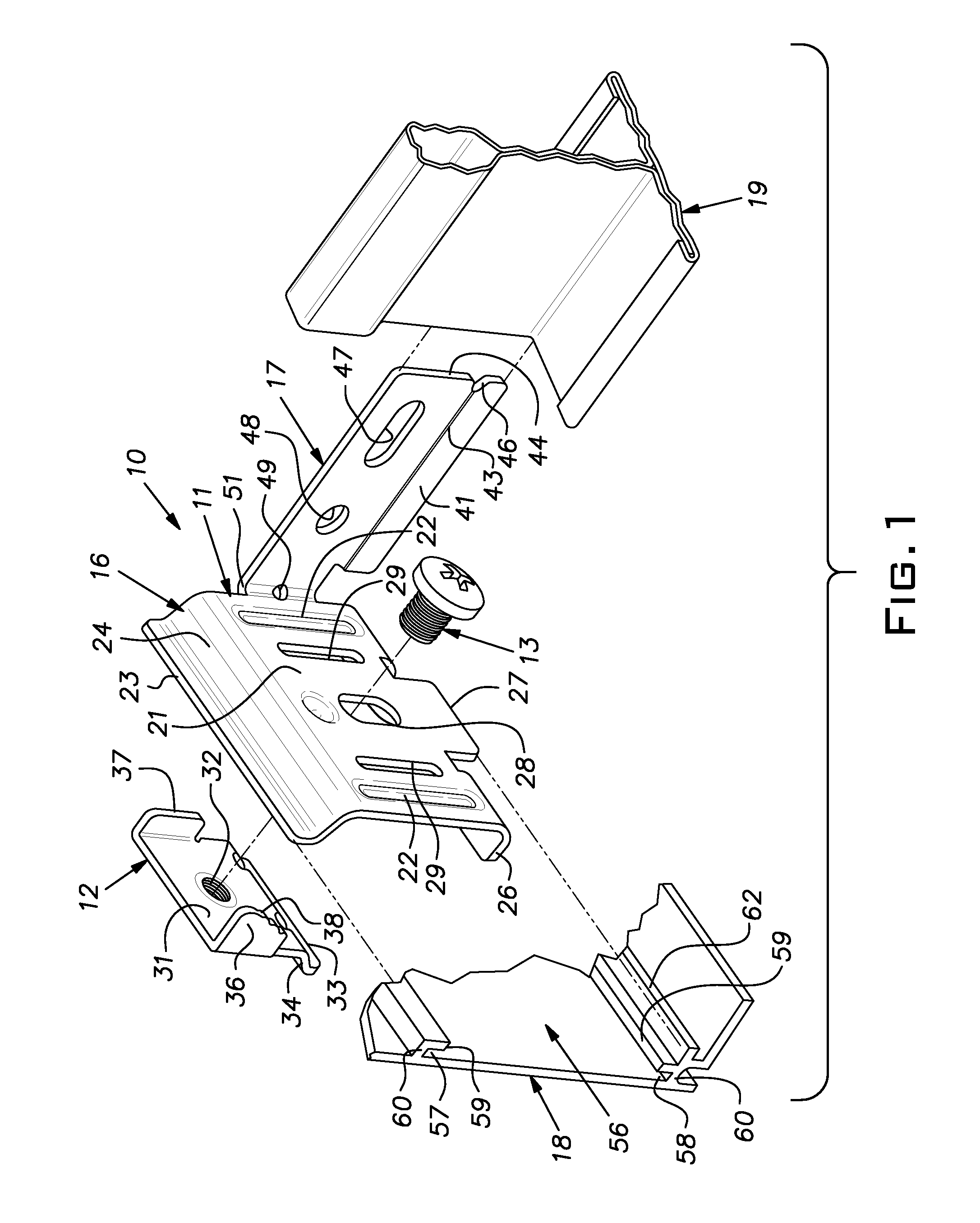
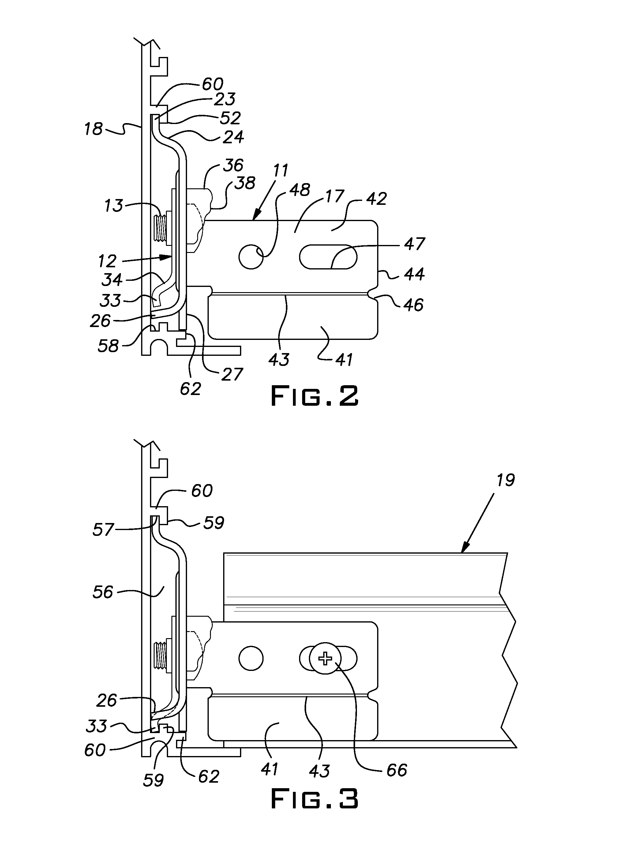
[0011]Referring now to the figures, an attachment clip 10 has a main body 11, a backer plate 12, and a machine screw 13. The main body 11 and backer plate 12 are preferably shaped from steel sheet stock, of for example 19 gauge zinc plated material, into their illustrated configurations. The main body 11 has intersecting legs 16, 17 which can be supplied in a right angle configuration and which in use typically lie in vertical planes. A larger one of the legs 16 attaches with a trim strip 18 and a smaller one of the legs 17 attaches with a grid runner 19. It will be understood by those working in the art that, while only one grid runner is illustrated, a typical suspension grid will have numerous grid runners intersecting one or more trim strips 18.

[0012]The leg 16 has a generally planar rectangular mid-section 21 reinforced with vertical embossments 22 adjacent its ends. At an upper side, the leg 16 has a forwardly offset upstanding flange 23 joined to the mid-section 21 with a web...


PUM


Abstract

A clip having a first leg for attaching to a trim strip and a second leg for attaching to a grid runner, the first leg having a backer plate attached with a screw through a slot, a head of the screw on a side of the first leg facing the second leg, the backer plate on the other side of the first leg, an upper edge of the first leg in a downwardly facing groove on a backside of the trim strip, the backer plate fitting between a depending free edge of the upper groove and an upstanding edge of a lower upwardly facing groove when the screw is up in the slot, and being received in the lower groove when the screw is down in the slot and clamping between the upstanding edge and a rear face of the trim strip when the screw is tightened.

Description

[0001]This application claims the benefit of U.S. provisional patent application Ser. No. 61 / 605,473, filed Mar. 1, 2012.[0002]The invention relates to a clip for attaching perimeter trim to a suspended ceiling grid.BACKGROUND OF THE INVENTION[0003]Suspended ceiling systems can include so-called island ceilings and fascias where all or a part of a perimeter of a ceiling is spaced from any wall. Various trim products and related accessories have been developed to provide a finished look for these wall-free ceiling perimeters. One style of trim is an aluminum extrusion formed with integral, mutually facing channels forming an attachment track on a rear face of the extrusion.[0004]Clips have been devised to attach the perimeter trim to suspended ceiling grid runners. U.S. Pat. No. 7,930,864 discloses an example of the prior art. Prior art clips, when being installed, can cause distortion of the trim if overly tightened, and can be expensive to manufacture. Thus, there has been a need f...

Claims


Application Information

Patent Timeline
Patent Type & Authority Applications(United States)
IPC IPC(8): E04B9/10
CPCE04B9/10E04B9/127E04B9/30E04B9/068
Inventor GULBRANDSEN, PEDERMIKLOSZ, MARKJACKSON, NICHOLASOSHGAN, STEPHENWASCOW, JOEBRUCE, JEREMY
Owner USG INTERIORS INC
Why Eureka
Try Eureka