Gas cylinder actuator with overtravel safety device

a safety device and actuator technology, applied in the direction of machines/engines, engines without rotary main shafts, shock absorbers, etc., can solve the problems of unusable actuators, unsustainable internal overload of actuators, harming operators in the vicinity,

Active Publication Date: 2013-09-05
SPECIAL SPRINGS SRL
View PDF11 Cites 18 Cited by
  • Summary
  • Abstract
  • Description
  • Claims
  • Application Information

AI Technical Summary

Benefits of technology

[0017]The aim of the present invention is to provide a gas cylinder actuator with overtravel safety device that is capable of obviating the drawbacks revealed by gas cylinder actuators and safety devices of the known type.

Problems solved by technology

These gas cylinder actuators are typically but not exclusively used for devices such as dies, molding presses and the like, in which they can be subjected to situations of high internal pressure or of impact with the associated parts of a press or of a die, such that they can be damaged; this damage can cause said gas cylinder actuator to become unusable, requiring replacement and stopping of the machine or system in which it is placed to work, but it can also be such as to harm an operator who is in the vicinity, as in the case of an explosion due to an uncontrolled pressure increase.
This overtravel can be caused for example by an unexpected increase in load on the stem of the actuator, which forces said stem to retract into the body of the actuator over an unexpected length, causing an internal overload of the actuator that can be unsustainable for the structure of the actuator as a whole.
The actuator can thus splay or break in the connecting points between the parts that compose it, or its sealing elements can fail, and in all these cases an unexpected, unwanted and dangerous rapid escape of gas can occur.
Both cited safety systems for gas cylinder actuators, despite being effective, have drawbacks.
A first drawback is linked to the fact that both technical solutions provide for the breakage of a part that is designed to allow the controlled escape of pressurized gas.
Therefore, in order to restore the full functionality of said gas cylinder actuator the part needs to be replaced, consequently requiring labor as well as spare parts.
A further drawback resides in the fact that the provision of said parts preset for breaking must be extremely precise, since it is essential that these parts break exactly at the preset stress.
Otherwise, if the parts preset for breaking do not break in the presence of the design loads, or break with loads lower than the design values, the gas cylinder actuator would not be safe.
Moreover, in the cited known gas cylinder actuators, the parts designed to break in the case of overtravel are arranged inside the gas cylinder actuator and therefore any breakage thereof is not immediately visually detectable.

Method used


Image

  • Gas cylinder actuator with overtravel safety device
  • Gas cylinder actuator with overtravel safety device
  • Gas cylinder actuator with overtravel safety device

Examples


first embodiment

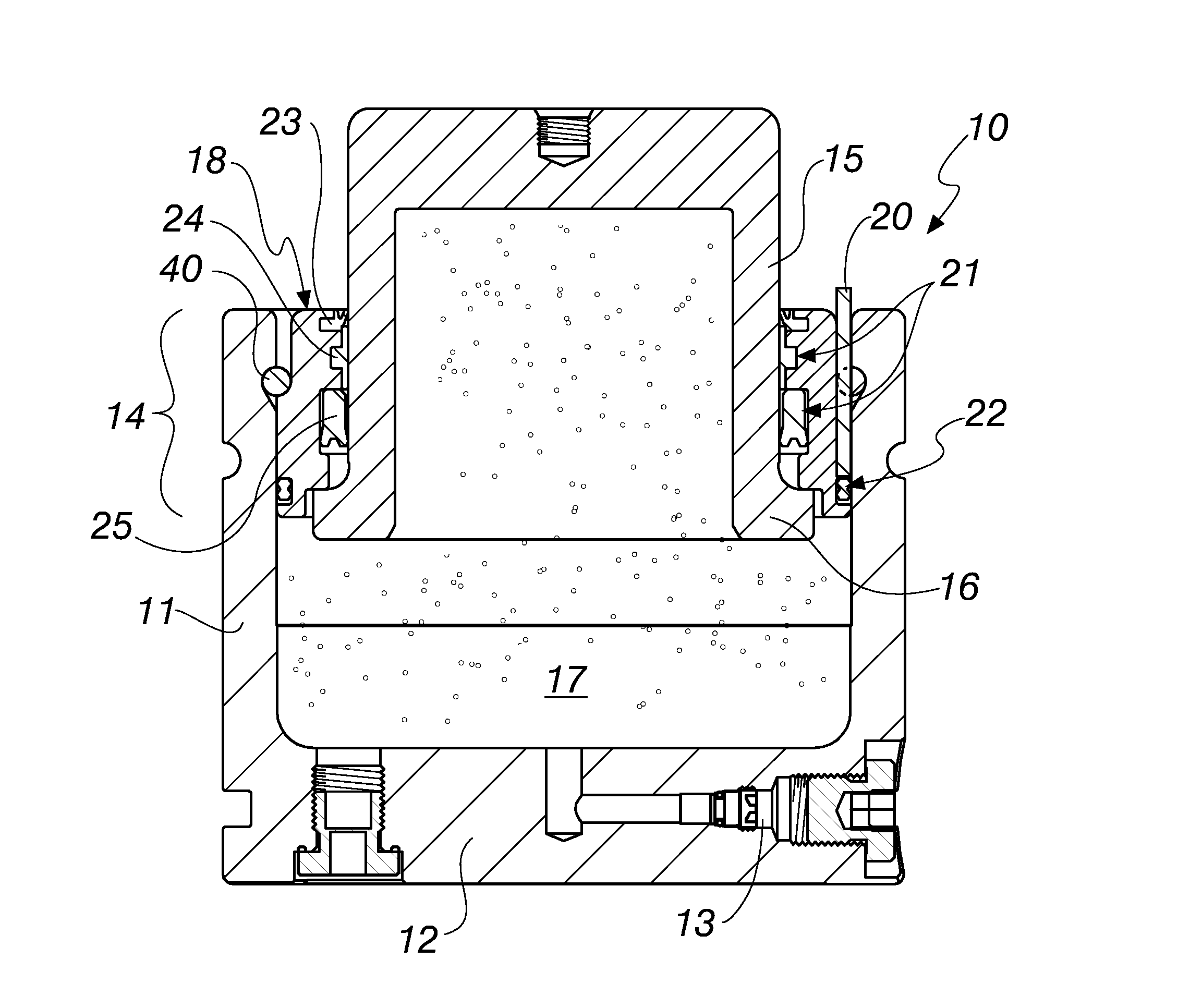
[0048]With reference to the figures, a gas cylinder actuator with overtravel safety device according to the invention is designated, in its first embodiment, shown in FIGS. 1 to 5, by the numeral 10.

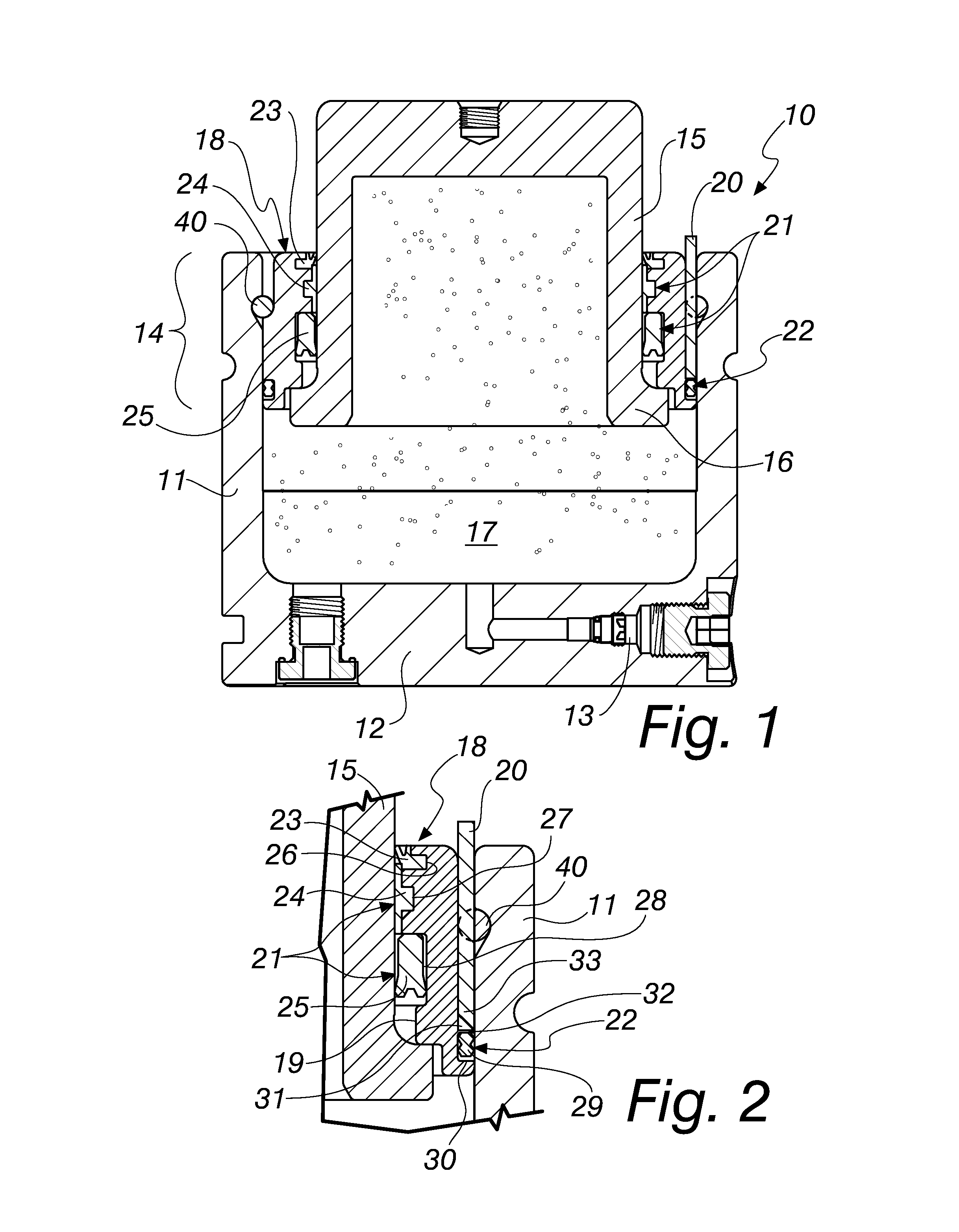
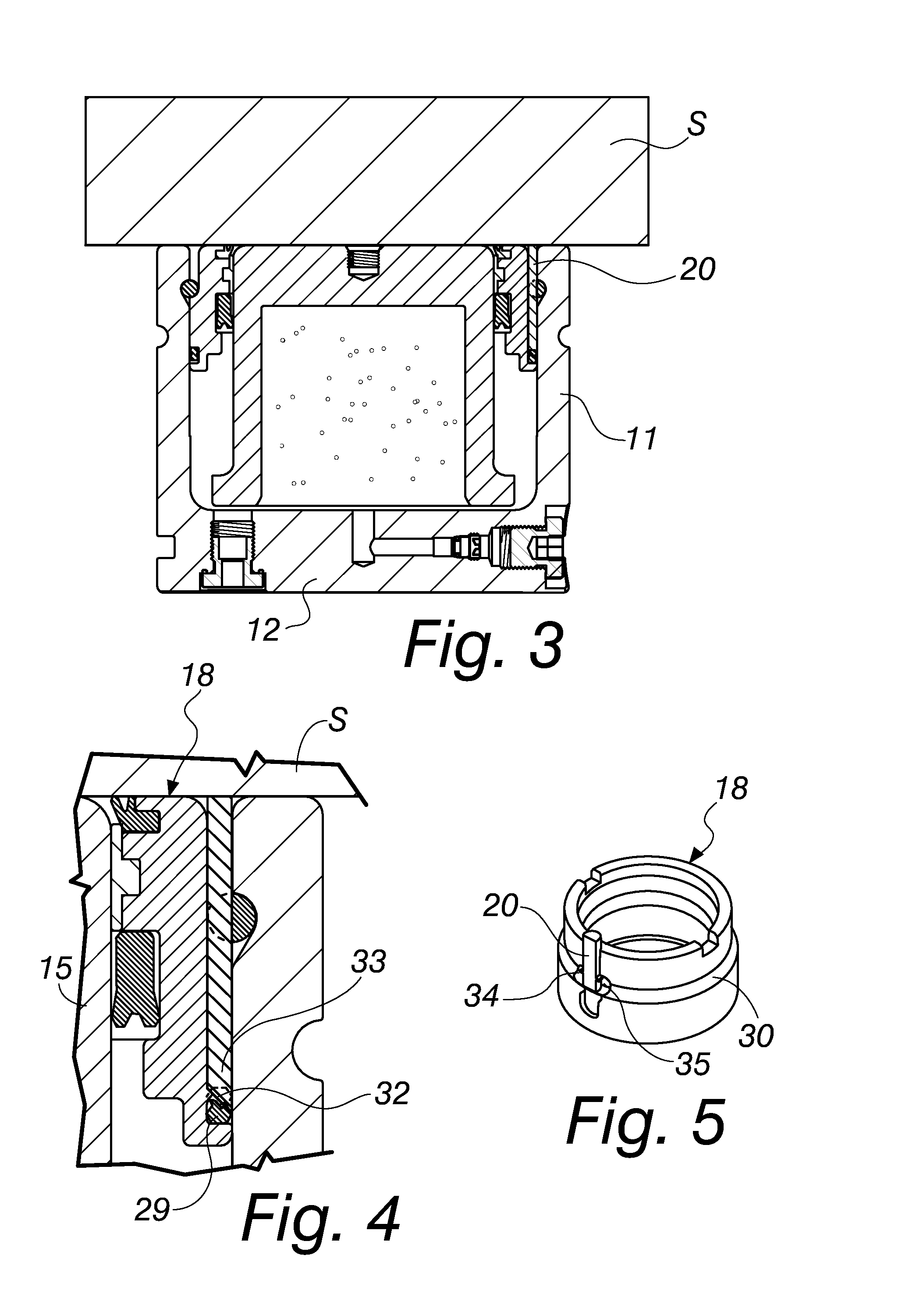
[0049]The gas cylinder actuator 10 comprises a tubular jacket 11 for gas containment, which is closed hermetically at one end by a bottom 12 provided with a gas filling valve 13 and at the opposite end by a head portion 14, which is provided with a hole for the passage of a stem 15 with a piston 16.

[0050]The jacket 11, the bottom 12 and the piston 16 form the chamber 17 for compression and expansion of the gas.

[0051]The head portion 14 comprises an annular body 18, which is fixed inside the jacket 11, with a central hole 19 for the passage of the stem 15 with the interposition of dynamic sealing means 21, described in more detail hereinafter.

[0052]Static sealing means 22, also described in more detail hereinafter, are interposed between the annular body 18 and the jacket 11.

[0053]An elem...

second embodiment

[0068]FIGS. 6 to 8 illustrate a gas cylinder actuator according to the invention, generally designated by the reference numeral 110.

[0069]In this second embodiment of the gas cylinder actuator according to the invention 110, the dynamic sealing means 121 are constituted for example by a stem scraper ring 123, by a gasket 125 and by a stem guiding band 124, each accommodated within a corresponding annular slot 126, 127 and 128.

[0070]The static sealing means 122 are constituted, again by way of non-limiting example of the invention, by an elastic ring 129, which is arranged within a corresponding annular slot 130.

[0071]In this second embodiment of the gas cylinder actuator 110 according to the invention, the control element 120 is constituted by a plug that is screwed onto the face 141 of the jacket 111 that is directed toward the slider S; the control element 120 blocks a safety discharge hole 142 that is formed in the jacket 111 and connects the chamber 117 to the outside.

[0072]The ...

third embodiment

[0078]FIGS. 9 to 12 illustrate a gas cylinder actuator according to the invention, designated therein by the reference numeral 210.

[0079]In such third embodiment of the gas cylinder actuator according to the invention 210, the dynamic sealing means 221 are constituted for example by a stem scraper ring 223, by a gasket 225 and by a stem guiding band 224, each accommodated in a corresponding annular slot 226, 227 and 228.

[0080]The static sealing means 222 are constituted, again by way of non-limiting example of the invention, by an elastic ring 229 arranged in a corresponding annular slot 230.

[0081]In this third embodiment of the gas cylinder actuator 210 according to the invention, the control element 220 is constituted by a shaped bushing, which is interposed between the piston stem 215 and the annular body 218 of the head portion 214 of the gas cylinder actuator 210.

[0082]The shaped bushing has an end portion 250 that protrudes in the direction of the main axis of the gas cylinder...


PUM


Abstract

A gas cylinder actuator with overtravel safety device, comprising a tubular jacket for gas containment, which is closed hermetically at one end by a bottom provided with a gas filling valve and at the opposite end by a head portion, which is provided with a hole for the passage of a stem with a piston, the jacket, the bottom and the piston forming the gas expansion and compression chamber.
The head portion comprises an annular body, which is fixed internally to the jacket, and is provided with a central hole for the passage of the stem with the interposition of dynamic sealing elements, static sealing elements being interposed between the annular body and the jacket and an element for controlling the descending motion of a slider of a press with which the actuator is associated being provided and protruding from the annular body or from the jacket, the control element being preset to selectively move or break or deform in order to break or deform or render ineffective in general the static and dynamic sealing elements.

Description

[0001]The present invention relates to a gas cylinder actuator with overtravel safety device.BACKGROUND OF THE INVENTION[0002]Gas cylinder actuators generally are formed by a tubular jacket for gas containment that is closed hermetically at one end by a bottom provided with a gas filling valve and, at the opposite end, by a head portion that is provided with a hole for the passage of a stem with a piston, which translates inside said jacket; the jacket, the bottom and the head portion form the stroke compartment for the piston, while said piston, with the jacket and the bottom, forms the chamber for the compression and expansion of the gas.[0003]These gas cylinder actuators are typically but not exclusively used for devices such as dies, molding presses and the like, in which they can be subjected to situations of high internal pressure or of impact with the associated parts of a press or of a die, such that they can be damaged; this damage can cause said gas cylinder actuator to be...

Claims


Application Information

Patent Timeline
Patent Type & Authority Applications(United States)
IPC IPC(8): F16J10/00
CPCF16J10/00F16F2230/24F16F9/0218F16F9/36F16F2230/06F16F9/02F16F9/346F16F9/3242F16F9/435F16J10/02
Inventor CAPPELLER, AUGUSTOCAPPELLER, ALESSANDROCAPPELLER, DANTE
Owner SPECIAL SPRINGS SRL
Why Eureka
Try Eureka