Highly uniform spunbonded nonwoven fabrics

a non-woven fabric, high-quality technology, applied in the direction of catheters, filtration separation, separation processes, etc., can solve the problems of catheter tube holders not providing adequate adhesion between the patient's skin and the catheter insertion site, and the catheter anchoring and supporting system and devices do not address the desirable, so as to reduce the risk of contamination, reduce the risk of patient infection, and easily secure the catheter to the patient's skin

Inactive Publication Date: 2013-09-05
FIBERWEB INC +1
View PDF1 Cites 1 Cited by
  • Summary
  • Abstract
  • Description
  • Claims
  • Application Information

AI Technical Summary

Benefits of technology

[0010]An object of the present catheter tube anchoring device to reduce the risk of contamination of a catheter through contact with non-sterile surfaces, thereby reducing the risk of patient infection.
[0011]Another object of the present catheter tube anchoring device is to make the starting of an I.V. much easier and faster than permitted by prior art devices.
[0012]Yet another object of the present catheter tube anchoring device is to easily secure a catheter to a patient's skin.
[0013]Still further, another object of the present catheter tube anchoring device is to substantially immobilize the IV to the skin of a patient, thereby reducing pain caused by movement of the IV in relation to the patient.

Problems solved by technology

However, these catheter anchoring and supporting system and devices do not address the desirable feature of aiding in the insertion of a catheter cannula into a catheter insertion site (e.g., a vein) of a patient.
Further, these catheter tube holders do not provide adequate adhesion between the patient's skin and the catheter insertion site to prevent a substantial displacement of the inserted cannula from the insertion site such as when any outward force is applied to the catheter tubing when moving a patient or when a patient is moving the area having the cannula inserted therein.

Method used


Image

  • Highly uniform spunbonded nonwoven fabrics
  • Highly uniform spunbonded nonwoven fabrics
  • Highly uniform spunbonded nonwoven fabrics

Examples


Embodiment Construction

Overview

[0051]The claimed subject matter is now described with reference to the drawings, wherein like reference numerals are used to refer to like elements throughout. In the following description, for purposes of explanation, numerous specific details are set forth in order to provide a thorough understanding of the claimed subject matter. It may be evident, however, that the claimed subject matter may be practiced without these specific details. In other instances, well-known structures and devices may be shown in block diagram form in order to facilitate describing the claimed subject matter.

[0052]Moreover, the word “exemplary” is used herein to mean serving as an example, instance, or illustration. Any aspect or design described herein as “exemplary” is not necessarily to be construed as preferred or advantageous over other aspects or designs. Rather, use of the word exemplary is intended to present concepts in a concrete fashion. As used in this application, the term “or” is i...


PUM

PropertyMeasurementUnit
diameteraaaaaaaaaa
diameteraaaaaaaaaa
temperatureaaaaaaaaaa

Abstract

A catheter anchoring system, apparatus and method for securing a catheter to a patient's skin, having two flexible side members and a cross-member therebetween to which a retaining assembly is mounted. The retaining assembly may hold a catheter hub at an angle for patient comfort. Gripping tabs secure to each retaining assembly side are gripped while advancing a cannula guide needle into the patient's vein and while attaching the catheter hub to a medical accessory, such as intravenous (I.V.) tubing, for increased patient comfort, reduction of the risk in contamination and patient infection, and to more easily and quickly start an I.V.

Description

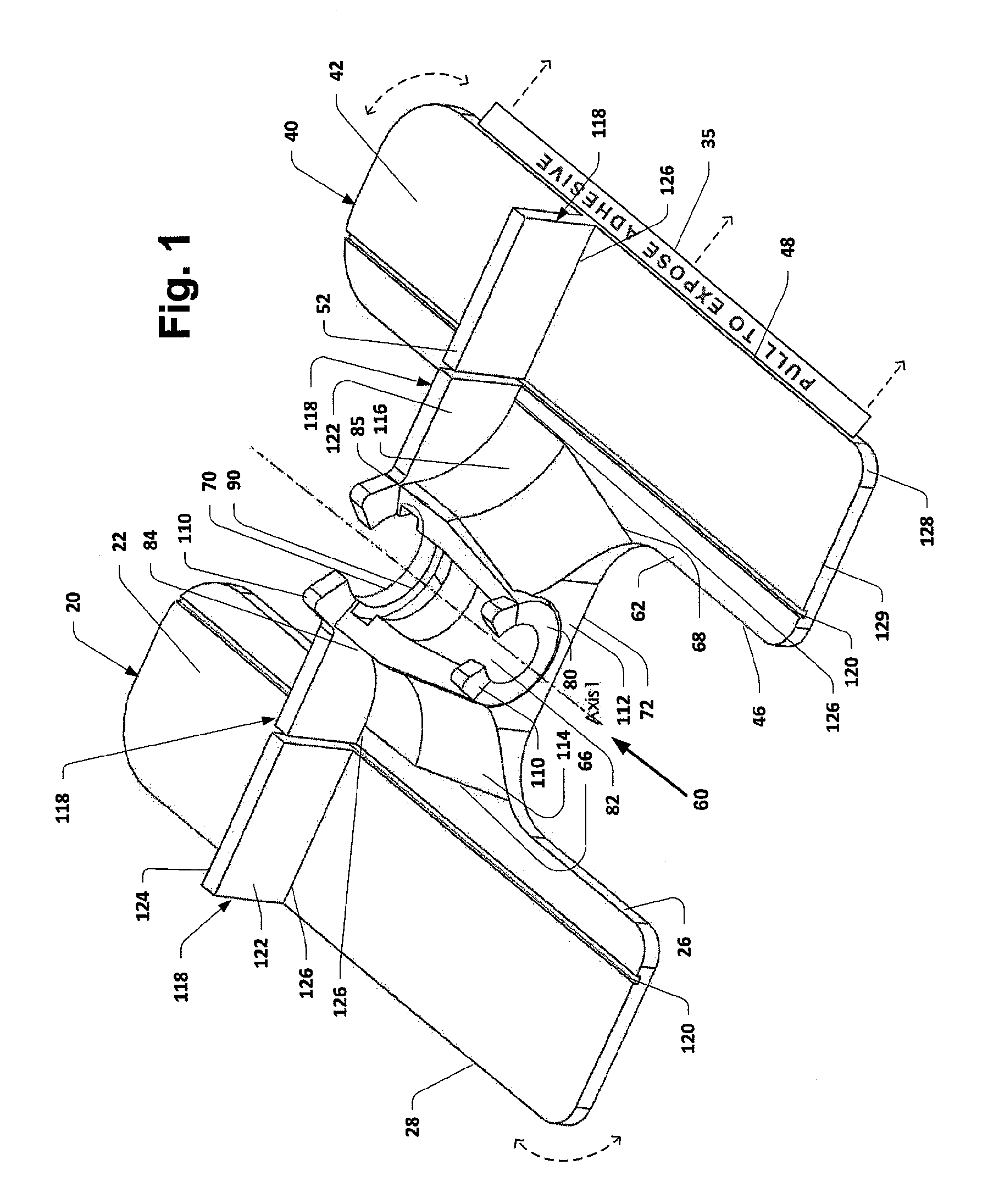
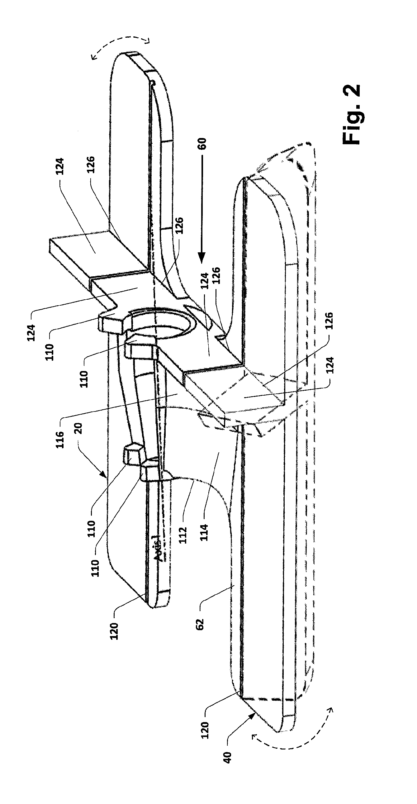
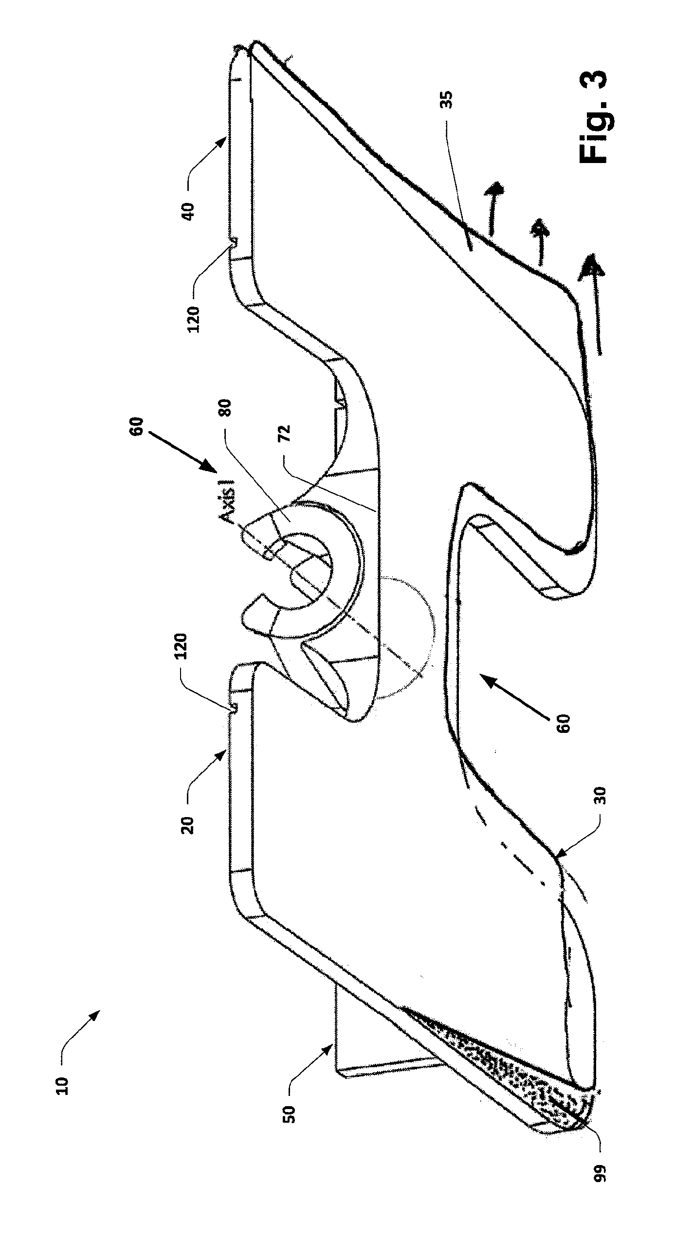
TECHNICAL FIELD[0001]The subject disclosure relates to catheter anchoring and supporting devices, and more specifically relates to catheter anchoring system, apparatus and method characterized by a removably mountable anchoring device for receiving a catheter hub of a catheter assembly, such that the anchoring device may be used as a guide to insert a cannula guide needle and associated cannula (e.g., intravenous cannula) of a catheter assembly into a patient's vein. Mounting the anchoring device to the patient limits movement of the catheter assembly in relation to the patient after cannula insertion. The anchoring device may dispose the catheter cannula at a preferred angle in relation to the patient. The anchoring device is shaped to facilitate asepsis when wrapped with an aseptic dressing. The subject disclosure is particularly relevant to aiding in the insertion of an intravenous (I.V.) cannula, increasing patient comfort and safety, reducing the risk of I.V. site contamination...

Claims


Application Information

Patent Timeline
Patent Type & Authority Applications(United States)
IPC IPC(8): D04H3/011
CPCA61M25/02A61M2025/024D04H3/011A61M2025/028A61M2025/0266Y10T442/609Y10T442/681Y10T442/69Y10T442/611
Inventor BAKER, JR., JOHN F.
Owner FIBERWEB INC
Why Eureka
Try Eureka