Turbine generator stator core attachment technique

a technology for stator cores and generators, applied in the direction of dynamo-electric machines, electrical equipment, magnetic circuit shapes/forms/construction, etc., can solve the problems of rotors and/or frames, premature failure of generators, and lamination of vibrating vibrations

Inactive Publication Date: 2013-09-05
SIEMENS ENERGY INC
View PDF9 Cites 9 Cited by
  • Summary
  • Abstract
  • Description
  • Claims
  • Application Information

AI Technical Summary

Problems solved by technology

These forces can also distort the core geometric shape, cause the laminations to vibrate, and damage the core, rotor and/or frame.
Also, mechanical fatigue caused by these forces can lead to premature failure of the generator.
Unfortunately, to accommodate the various different core-to-frame attachment techniques, numerous and different attachment hardware components and weldments are required.
The exerted forces and loads produced by these attachment techniques are also di

Method used


Image

  • Turbine generator stator core attachment technique
  • Turbine generator stator core attachment technique
  • Turbine generator stator core attachment technique

Examples


Embodiment Construction

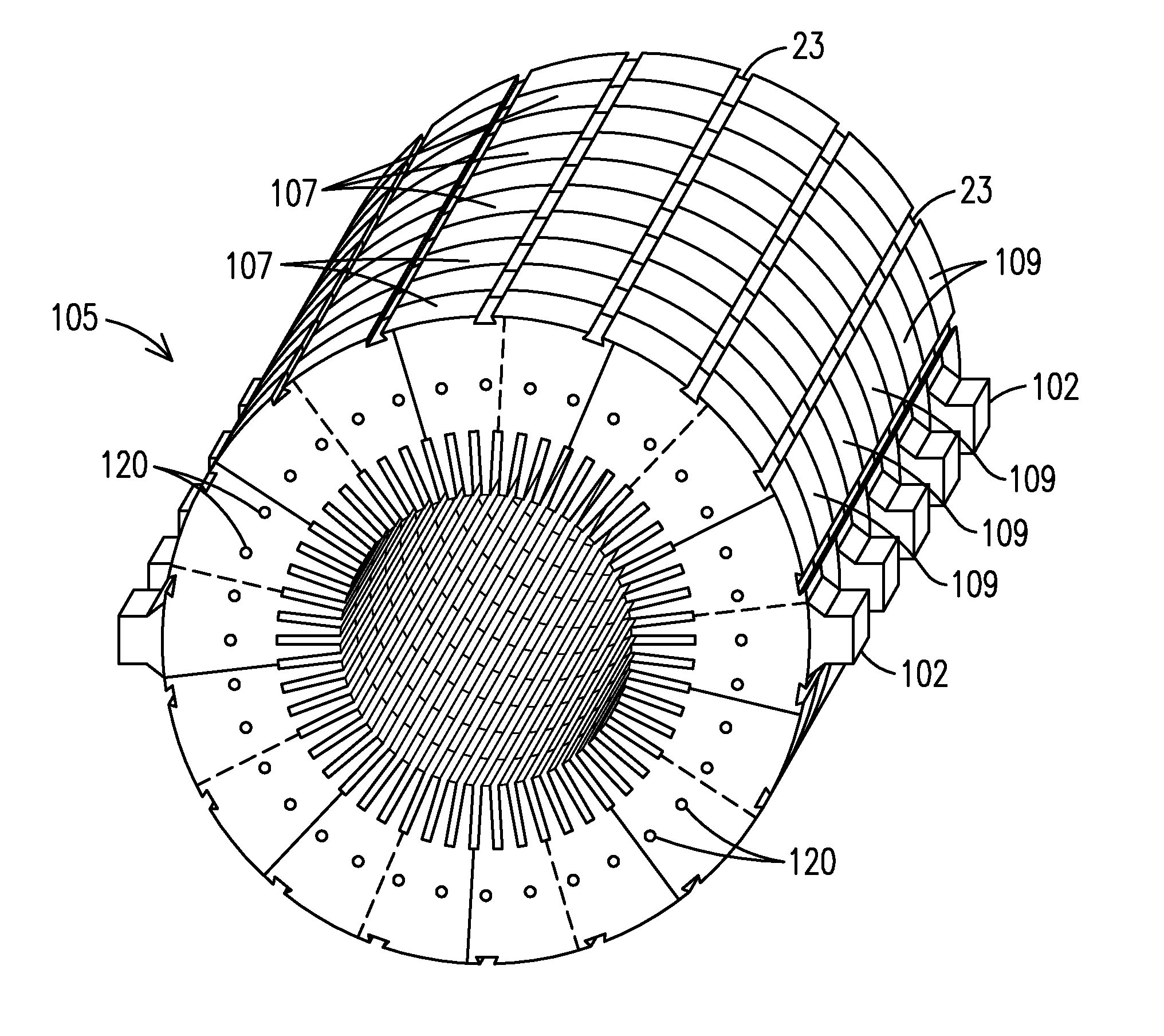
[0032]Stator core laminations are punched from electrical steel sheet. A single typical lamination comprises nine segments (or nine punchings) and thus nine punching operations (also referred to as stamping operations) are required to form the nine segments. A single punching die is used to punch the nine segments for a stator core of a given size and shape. Additional dies are utilized to punch the laminations for differently sized stator cores, where the core size depends on the power rating and size of the generator. This technique is especially valuable and efficient when a large number of identical punchings are required.

[0033]Today, most punchings are formed by a laser cutting operation. A cutting die is not required as the laser cutting process is controlled by a software program controlling a multi-axis laser cutter.

[0034]The present invention teaches core laminations having at least two tabs extending from a circumferential edge of the lamination. Preferably, the two tabs a...


PUM


Abstract

A stator core (105) including tabbed laminations (100) stacked face-to-face to form a plurality of tabbed lamination modules (107), with each tabbed lamination including a first tab (102) and a second tab (104) extending from a circumferential edge of the lamination. Non-tabbed laminations are also stacked face-to-face to form a plurality of non-tabbed lamination modules (109), each non-tabbed lamination lacking a tab. The tabbed lamination modules are stacked face-to-face in an alternating configuration with non-tabbed lamination modules. The tabs are used to attach the stator core to an inside surface of an electrical generator frame (2), such as by attaching the tabs to frame support rings (4) of the generator frame.

Description

FIELD OF THE INVENTION[0001]The present invention relates to electric power generators and more specifically to methods and apparatuses for attaching a stator core to a generator frame.BACKGROUND OF THE INVENTION[0002]The generator stator core is the largest monobloc component in a turbine-generator set. The stator core comprises thousands of thin steel laminations horizontally stacked and clamped together to form a cylindrical stator core disposed within a generator frame. Each lamination defines a central opening and thus when stacked, an axial opening extends through the core. The laminations are held together by a plurality of axial through-bolts that extend from end-to-end through the core.[0003]A rotor is disposed within the central opening and mechanically rotated by a rotating turbine. The rotor is responsive to an electrical current such that rotation generates electric current in stator windings. The stator current is supplied to electrical loads through a transmission and...

Claims


Application Information

Patent Timeline
IPC IPC(8): H02K1/18
CPCH02K1/16H02K1/18H02K1/185
Inventor ALLEN, DAVID T.MARRERO, JOSUE
Owner SIEMENS ENERGY INC
Why Eureka
Try Eureka