
Method and apparatus of handling in-device co-existence interference in a multi-radio environment

a multi-radio environment and coexistence technology, applied in the field of wireless communication systems, can solve problems such as interference to the ism receiver, 10-30 db isolation, interference to the receiver of another radio,

Active Publication Date: 2013-09-05
SAMSUNG ELECTRONICS CO LTD
View PDF13 Cites 6 Cited by
  • Summary
  • Abstract
  • Description
  • Claims
  • Application Information

AI Technical Summary

Benefits of technology

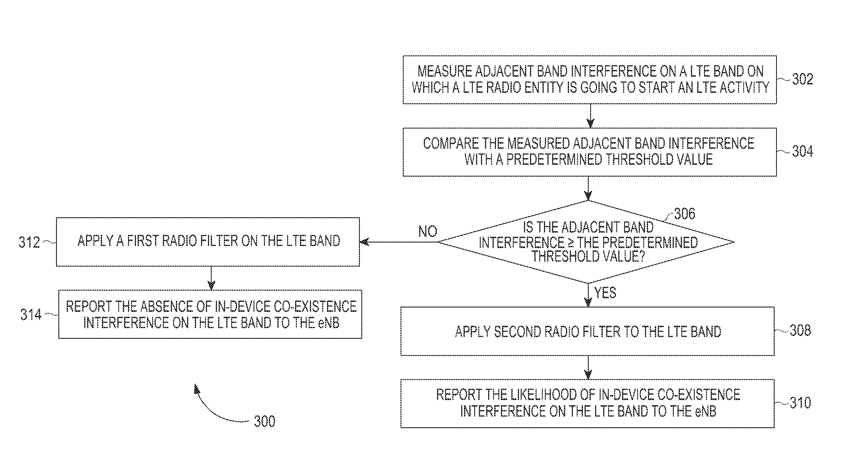
The present invention provides a method and apparatus for handling in-device co-existence interference in a user equipment (UE) having multiple radio entities. The invention addresses the problem of interference between adjacent bands caused by small form factors of the radio technologies and limited dynamic range of power amplifiers, analog to digital converters, and out of band emission due to imperfect filtering. The invention provides a solution for measuring adjacent band interference value, comparing it with a predetermined threshold value, and reporting it to an eNB, so that inter-device co-existence interference can be managed effectively. The invention also includes a system that includes a coordinator for handling in-device co-existence interference between the LTE and ISM radio entities.

Problems solved by technology

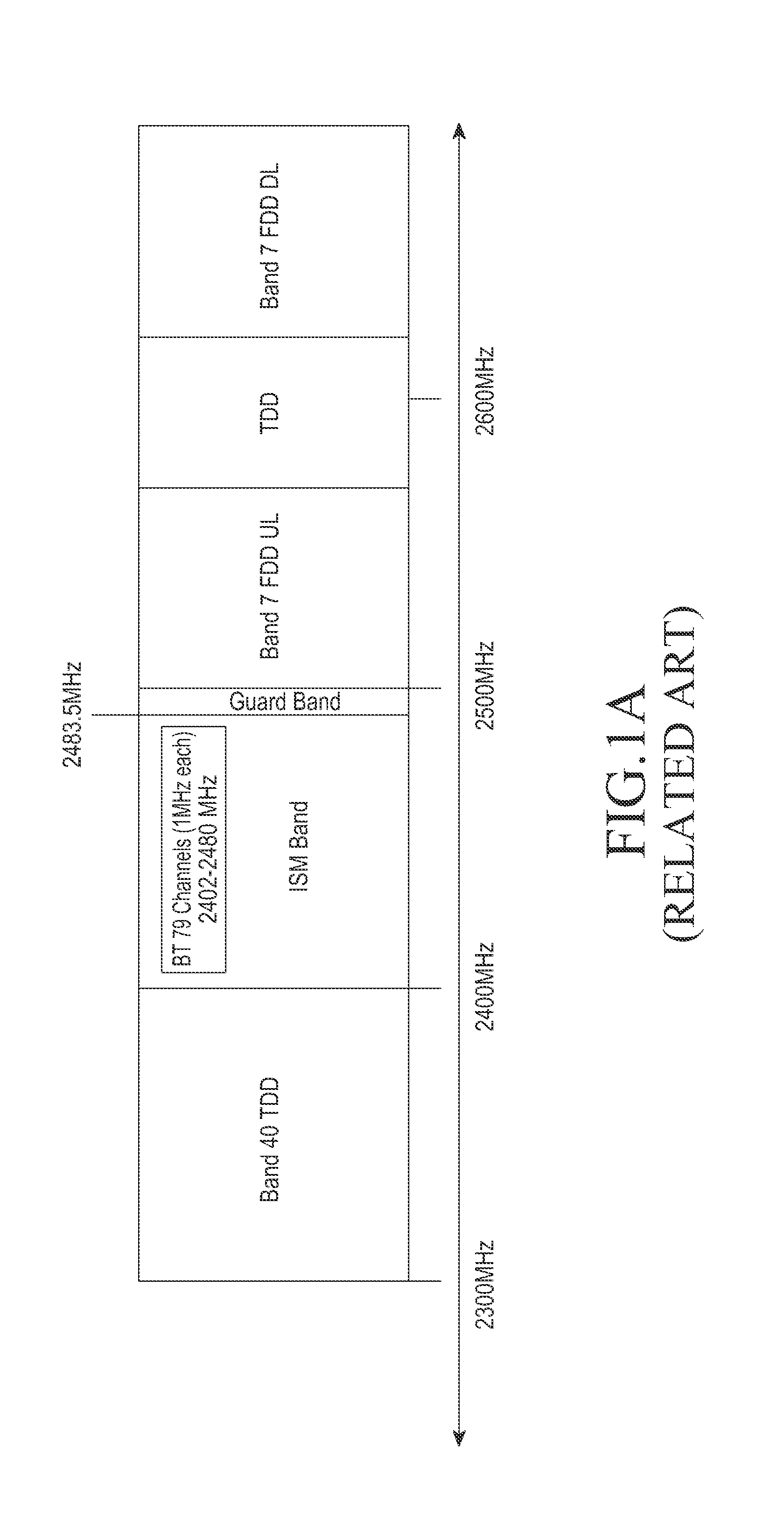
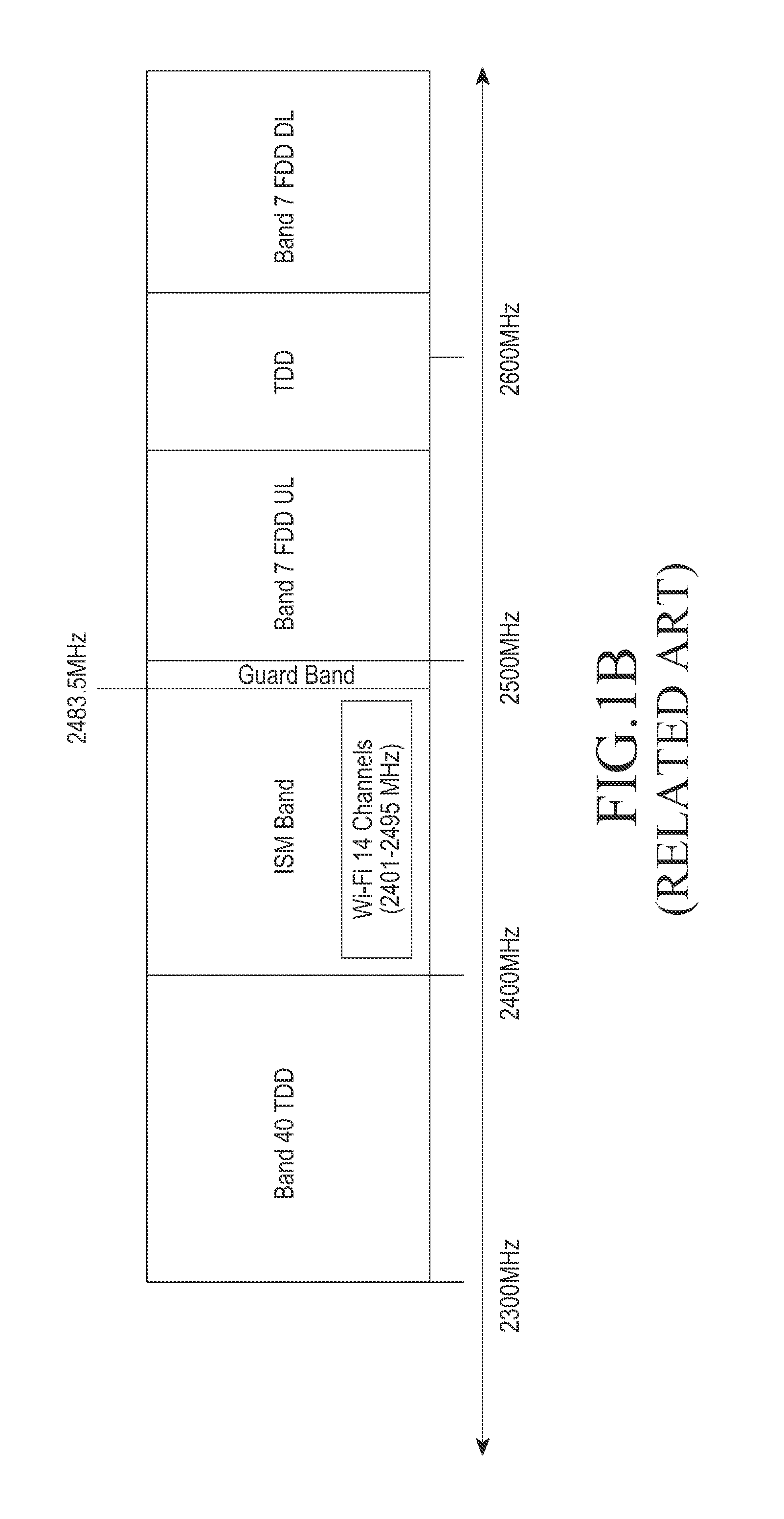
However, small form factors of a User Equipment (UE) may provide only 10-30 dB isolation.
As a result, a transmitter of one radio may affect a receiver of another radio.
For example, a small form factor of the UE may cause interference from transmission using ISM technology to the receiver of cellular technologies such as LTE or WiMax.
Similarly, the transmitter of cellular technology may cause interference to the ISM receiver.
The main cause of in-device co-existence issues may be because of receiver blocking due to a limited dynamic range of a power amplifier, an analog to digital converter and an out of band emission due to imperfect filtering.

Method used


Image

  • Method and apparatus of handling in-device co-existence interference in a multi-radio environment
  • Method and apparatus of handling in-device co-existence interference in a multi-radio environment
  • Method and apparatus of handling in-device co-existence interference in a multi-radio environment

Examples


Embodiment Construction

[0032]The following description with reference to the accompanying drawings is provided to assist in a comprehensive understanding of exemplary embodiments of the invention as defined by the claims and their equivalents. It includes various specific details to assist in that understanding but these are to be regarded as merely exemplary. Accordingly, those of ordinary skill in the art will recognize that various changes and modifications of the embodiments described herein can be made without departing from the scope and spirit of the invention. In addition, description of well-known functions and constructions may be omitted for clarity and conciseness.

[0033]The terms and words used in the following description and claims are not limited to the bibliographical meanings, but, are merely used by the inventor to enable a clear and consistent understanding of the invention. Accordingly, it should be apparent to those skilled in the art that the following description of exemplary embodi...


PUM


Abstract

A method and apparatus of handling in-device co-existence interference in a multi-radio environment are provided. The method includes measuring an adjacent band interference value indicating an amount of adjacent band interference in a Long Term Evolution (LTE) band associated with an LTE radio entity prior to switching the LTE radio entity to an active state from an inactive state, comparing the adjacent band interference value with a predetermined threshold value, and reporting in-device co-existence interference in the LTE band to an evolved Node B (eNB) according to an outcome of the comparing of the adjacent band interference value with the predetermined threshold value.

Description

PRIORITY[0001]This application is a National Stage application under 35 U.S.C. §371 of an International application filed on Nov. 8, 2011 and assigned application No. PCT / KR2011 / 008480, and claims the benefit under 35 U.S.C. §365(b) of an Indian patent application filed in the Indian Industrial Property Office on Nov. 8, 2010 and assigned Serial No. 3325 / CHE / 2010, the entire disclosure of which is hereby incorporated by reference.BACKGROUND OF THE INVENTION[0002]1. Field of the Invention[0003]The present invention relates to wireless communication systems. More particularly, the present invention relates to a method and apparatus of handling in-device co-existence in a multi-radio environment.[0004]2. Description of the Related Art[0005]Coexistence of Long Term Evolution (LTE) with the Industrial, Scientific and Medical (ISM) band technologies, such as Bluetooth, Wi-Fi and the like, and Global Navigation Satellite Systems (GNSS) should be provided as these technologies and systems a...

Claims


Application Information

Patent Timeline
Patent Type & Authority Applications(United States)
IPC IPC(8): H04B15/00H04W72/54
CPCH04B1/525H04W72/02H04W88/06H04B15/00H04J11/0066H04B1/1027H04B1/3805H04J11/0036H04W24/10
Inventor GANAPATHI, SARVESHA ANEGUNDIJAMADAGNI, SATISH NANJUNDA SWAMY
Owner SAMSUNG ELECTRONICS CO LTD
Learn More