
Sensor Fusion Algorithm

a technology of fusion algorithm and sensor, which is applied in the direction of electric controller, electric apparatus casing/cabinet/drawer, electric controller, etc., can solve the problems that the action of accessories may sometimes interfere with the operation of the host computing device, and the user experience may be adversely affected

Active Publication Date: 2013-09-05
MICROSOFT TECH LICENSING LLC
View PDF1 Cites 90 Cited by
  • Summary
  • Abstract
  • Description
  • Claims
  • Application Information

AI Technical Summary

Benefits of technology

This patent describes a way to control the behavior of a host device and its accessories based on their orientation relative to each other. It uses sensor fusion algorithms to combine information from different types of sensors to determine the overall position and orientation of the host and accessories. This information is used to control things like the display and input methods of the host device and accessories. Overall, this technology helps to make devices smarter and more intuitive to use.

Problems solved by technology

One challenge that faces developers of mobile computing devices is managing behaviors and interaction with accessory devices.
For instance, a host computing device may have limited control over how an accessory device behaves and thus actions of the accessory may sometimes interfere with operation of the host computing device.
Moreover, the user experience may be adversely affected by accessory devices that do not respond in a manner that is consistent with the host computing device.
Thus, integrated management of behaviors and interaction for accessory devices may be a challenging consideration for developers of mobile computing devices.

Method used


Image

  • Sensor Fusion Algorithm
  • Sensor Fusion Algorithm
  • Sensor Fusion Algorithm

Examples


example procedures

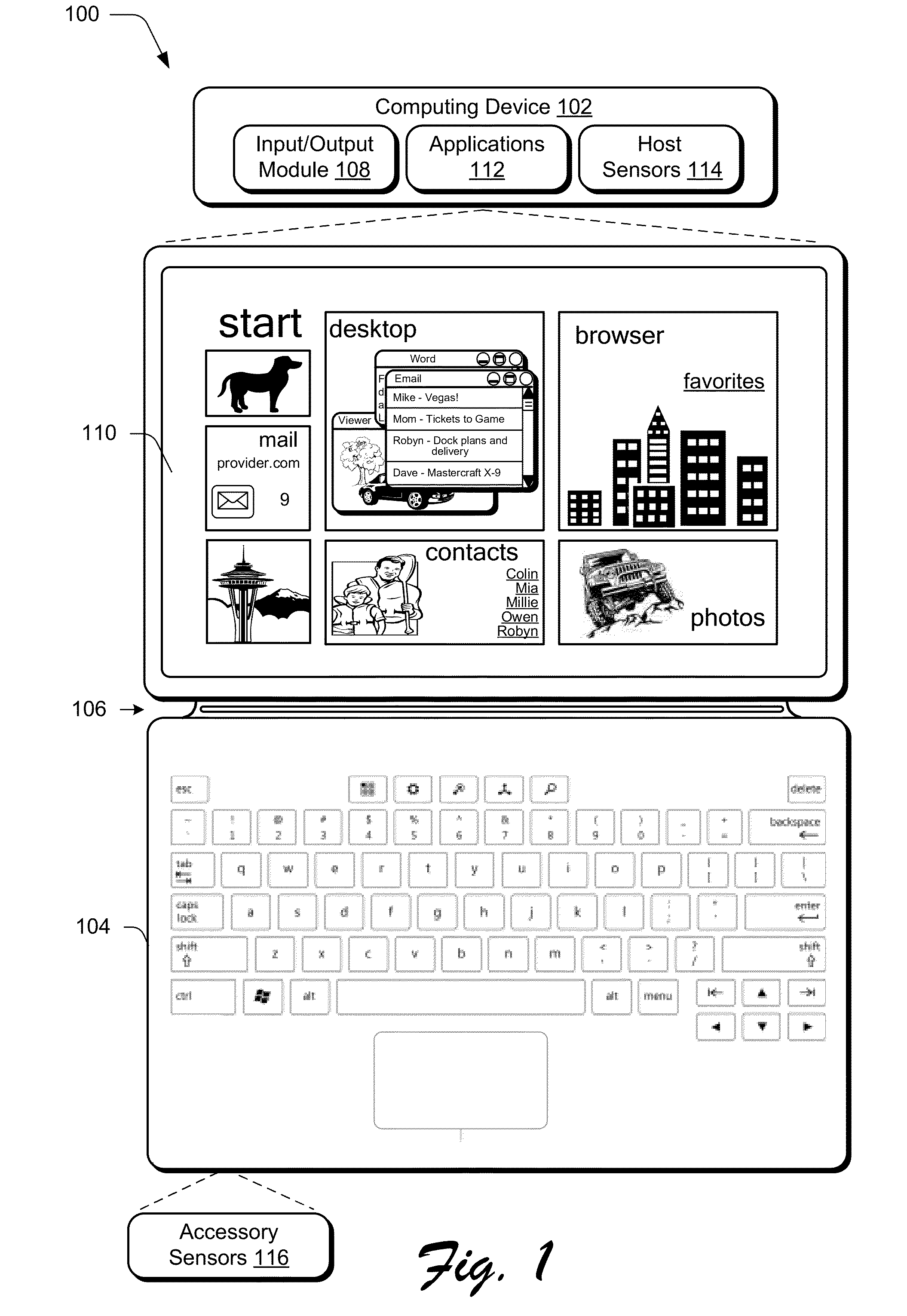
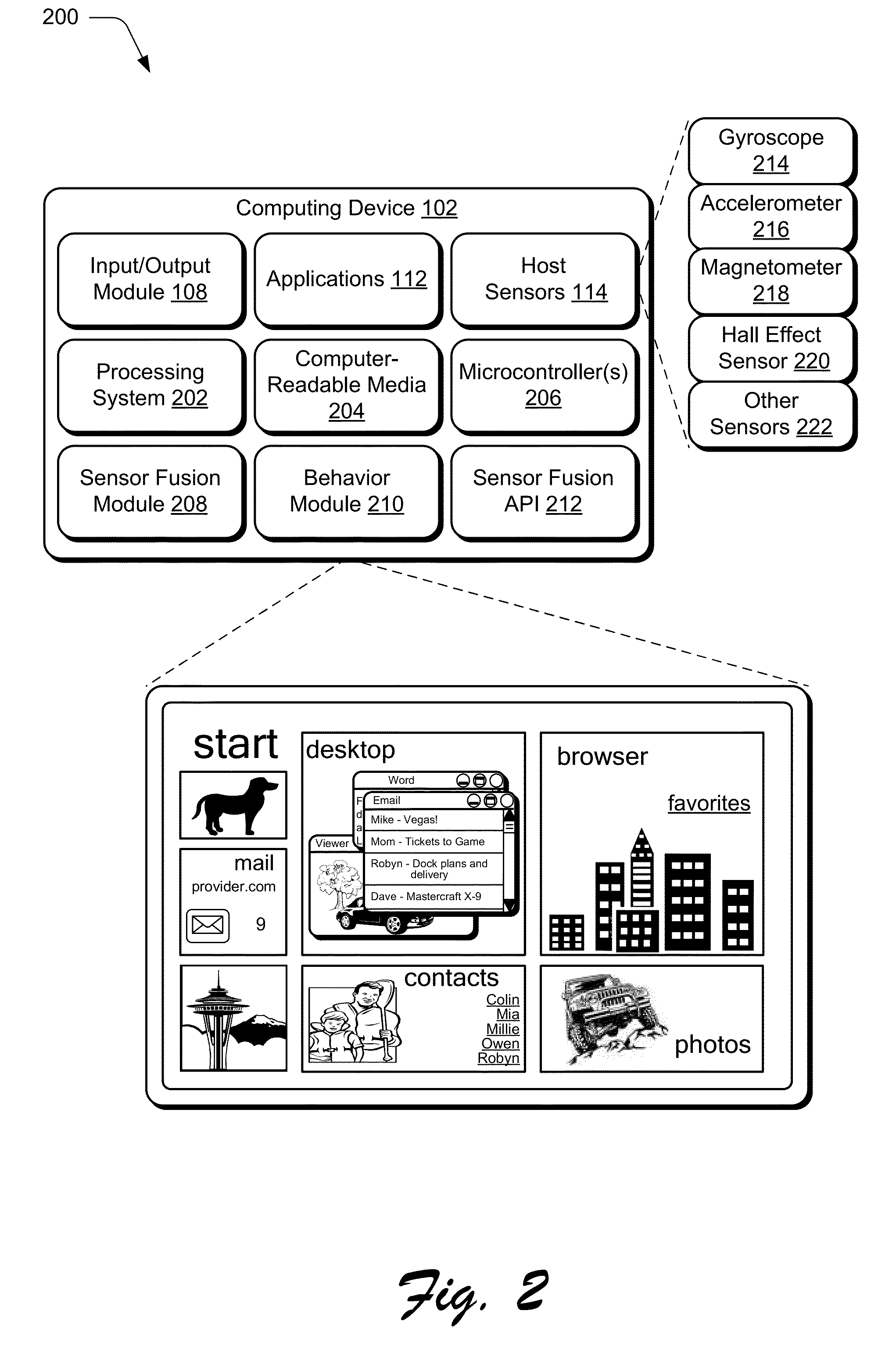
[0061]The following discussion describes sensor fusion algorithm techniques that may be implemented utilizing the previously described systems and devices. Aspects of each of the procedures may be implemented in hardware, firmware, software, or a combination thereof. The procedures are shown as a set of blocks that specify operations performed by one or more devices and are not necessarily limited to the orders shown for performing the operations by the respective blocks. In portions of the following discussion, reference may be made to the example operating environment 100 of FIG. 1, the example devices of FIGS. 2-3, and the example orientation shown in FIGS. 4-10, respectively.

[0062]FIG. 11 depicts an example procedure 1100 in which an orientation of an accessory relative to a host is computed. In at least some embodiments, the procedure may be performed by a suitably configured computing device, such as the example computing device 102 of FIG. 2 that includes or otherwise make us...


PUM

PropertyMeasurementUnit
angleaaaaaaaaaa
mechanicalaaaaaaaaaa
flexibleaaaaaaaaaa

Abstract

Sensor fusion algorithm techniques are described. In one or more embodiments, behaviors of a host device and accessory devices are controlled based upon an orientation of the host device and accessory devices, relative to one another. A combined spatial position and / or orientation for the host device may be obtained based on raw measurements that are obtained from at least two different types of sensors. In addition, a spatial position and / or orientation for an accessory device is ascertained using one or more sensors of the accessory device. An orientation (or position) of the accessory device relative to the host computing device may then be computed based on the combined spatial position / orientation for the host computing device and the ascertained spatial position / orientation for the accessory device. The relative orientation that is computed may then be used in various ways to control behaviors of the host computing device and / or accessory device.

Description

RELATED APPLICATIONS[0001]This application claims priority under 35 U.S.C. §119(e) to the following U.S. Provisional patent applications, the entire disclosures of each of these applications being incorporated by reference in their entirety:[0002]U.S. Provisional Patent Application No. 61 / 606,321, filed Mar. 2, 2012, Attorney Docket Number 336082.01, and titled “Screen Edge;”[0003]U.S. Provisional Patent Application No. 61 / 606,301, filed Mar. 2, 2012, Attorney Docket Number 336083.01, and titled “Input Device Functionality;”[0004]U.S. Provisional Patent Application No. 61 / 606,313, filed Mar. 2, 2012, Attorney Docket Number 336084.01, and titled “Functional Hinge;”[0005]U.S. Provisional Patent Application No. 61 / 606,333, filed Mar. 2, 2012, Attorney Docket Number 336086.01, and titled “Usage and Authentication;”[0006]U.S. Provisional Patent Application No. 61 / 613,745, filed Mar. 21, 2012, Attorney Docket Number 336086.02, and titled “Usage and Authentication;”[0007]U.S. Provisional P...

Claims


Application Information

Patent Timeline
Patent Type & Authority Applications(United States)
IPC IPC(8): G06F3/00
CPCG06F1/1618Y10T29/49826G06F1/1669G06F1/1681G06F3/0202G06F1/1684H05K5/0226H05K5/0234G06F1/1683G05B11/01H04M1/0216H04M1/0245H04M1/0254H04M1/72527G06F3/0416G06F3/002G06F3/01H01H13/702G06F3/0414G06F1/1656H01H13/704H01H13/82H01H13/79H01H13/78H01H13/785H01H2217/004G06F9/541G06F11/3089G06F13/102H01H13/14H01H13/703H01H2201/036H01H2205/006H01H2211/006G06F1/1662G06F3/023Y10T16/551Y10T16/5401G06F1/1654G06F3/0488G06F3/0487G06F1/1686H01H2211/004H01H2203/02H01H2217/01G06F3/02H01H2217/006H01H2227/032H01H13/807G06F3/04886Y02D10/00H04M1/72409G06F3/0233H01H2203/058H01H2203/036E05Y2201/46E05D11/1064E05F5/08F16M11/38G06F1/1637G06F1/166G06F1/1616H01H9/26H01H11/00H01H2213/016G06F3/0219
Inventor PEREK, DAVID R.SCHWAGER, MICHAEL A.DRASNIN, SHARONSEILSTAD, MARK J.
Owner MICROSOFT TECH LICENSING LLC
Learn More