Signature-reduced muzzle brake

a technology of muzzle brake and signature, applied in the field of muzzle brake, can solve the problems of action being taken against and skilled in the art would see this as questionable, and achieve the effect of reducing the intrinsic signatur

Active Publication Date: 2013-09-12
RHEINMETALL WAFFE MUNITION GMBH
View PDF6 Cites 26 Cited by
  • Summary
  • Abstract
  • Description
  • Claims
  • Application Information

AI Technical Summary

Benefits of technology

[0015]It is therefore an object of the invention to prov

Problems solved by technology

How one skilled in the art would see this is questionable.
This is detrimental in that

Method used


Image

  • Signature-reduced muzzle brake
  • Signature-reduced muzzle brake
  • Signature-reduced muzzle brake

Examples


Embodiment Construction

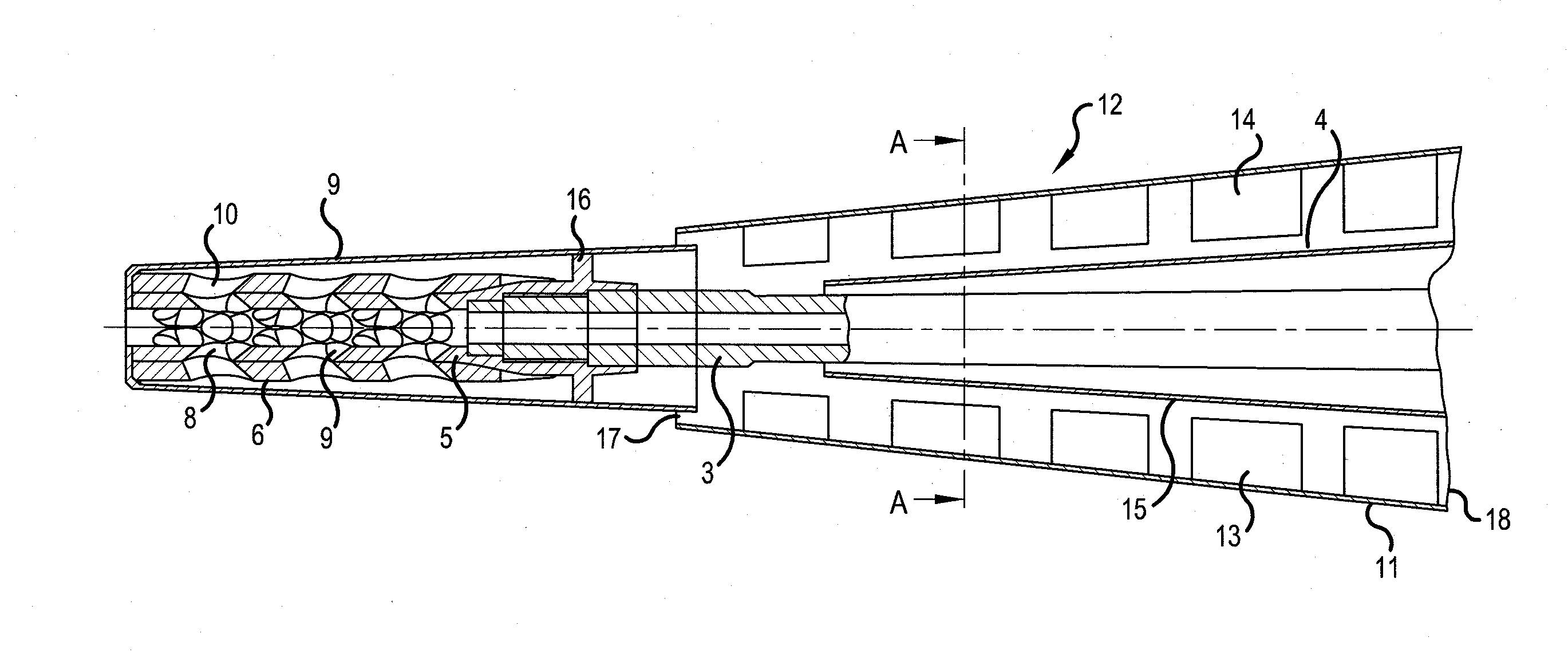
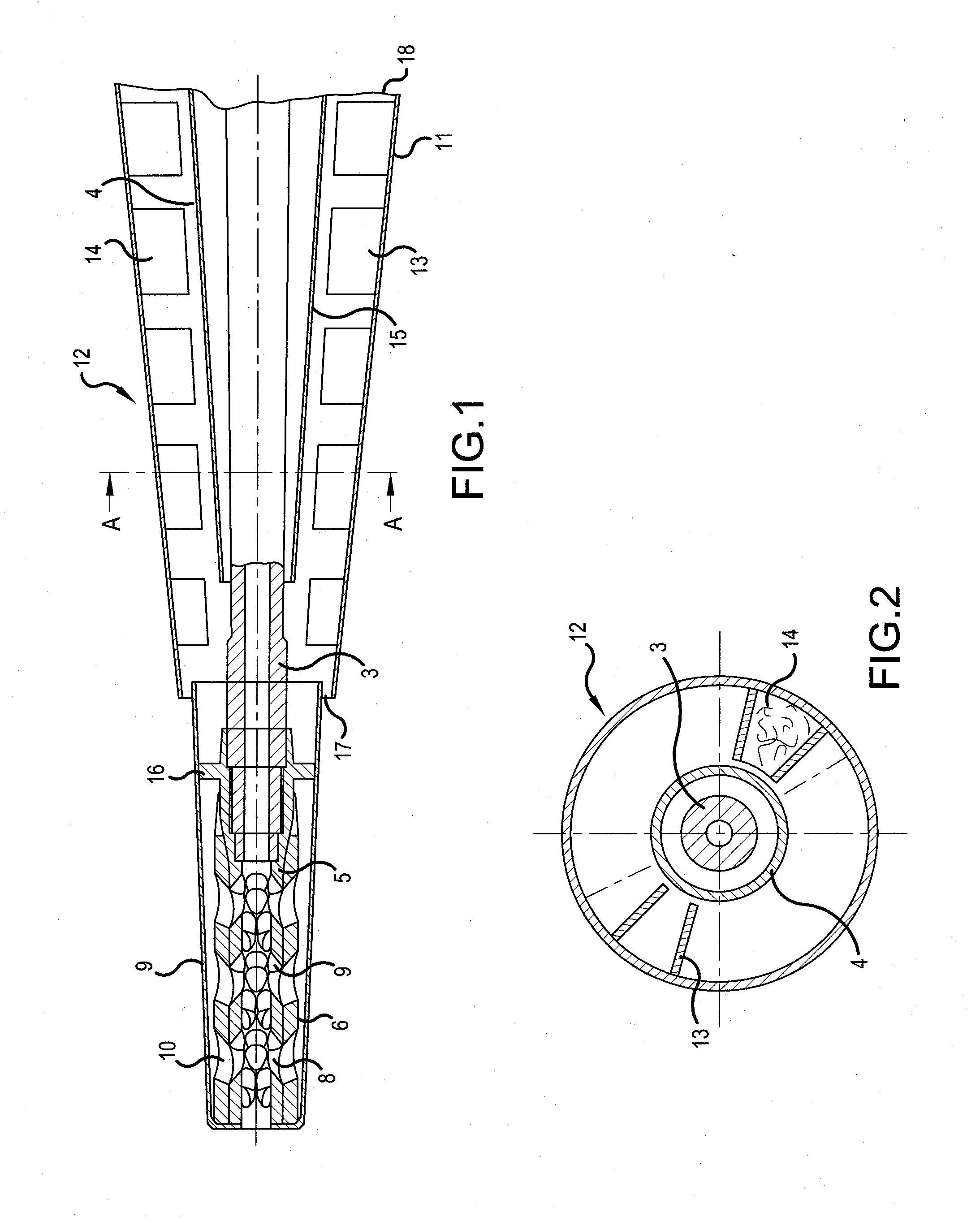
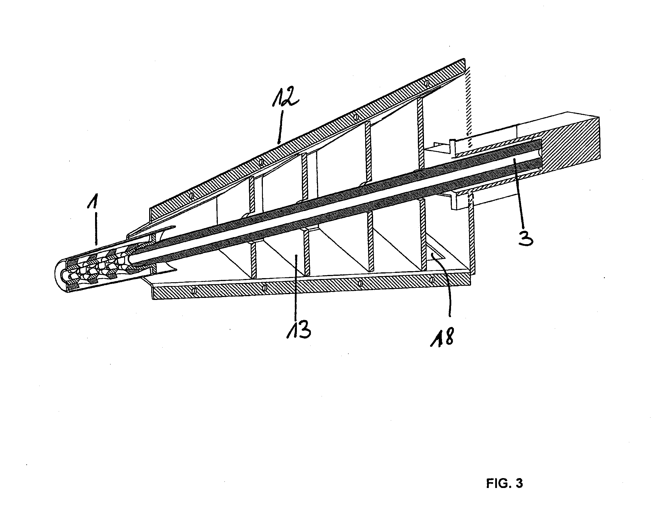
[0029]In a cross-sectional representation, FIG. 1 shows a muzzle brake 1 with a jacket 2, which can be attached to a gun barrel 3, for example by means of a screw fitting. In this exemplary embodiment, the gun barrel 3 is enclosed by a barrel mount 4.

[0030]The muzzle brake 1 is composed of a base sleeve 5, a deflecting sleeve 6, and a jacket tube 7. Taper bores 8 in the base sleeve 5 have bevels 9 so that the propellant gases can exit better. Taper bores 10 in the deflecting sleeve 6 provide for better expansion in the jacket tube 7. The bores 8, 10 have an oblique shape—becoming larger toward the outside in each case, similar to a taper bore—since this shape can depressurize the gas, so that a first cooling already takes place at this point. The two bores 8, 10 are matched to one another.

[0031]Adjoining the jacket tube 7 is a gas-reducing device 12, which in the simplest form can be a simple outer tube (not shown in detail). According to the concept of the invention, an additional ...


PUM


Abstract

A muzzle brake of a weapon or a weapons system for small- and medium-calibre weapons, that has a reduced outer signature with respect to heat and/or propellant gas emissions is provided. For this purpose, the propellant gas emerging from the barrel is diverted to the gas outlet openings of the muzzle brake in order to impinge on them to absorb the recoil, and is then made to pass further to the rear, and thereby cooled in a device.

Description

[0001]This nonprovisional application is a continuation of International Application No. PCT / EP2011 / 001996, which was filed on Apr. 19, 2011, and which claims priority to German Patent Application No. DE 10 2010 019 358.5, which was filed in Germany on May 6, 2010, and which are both herein incorporated by reference.BACKGROUND OF THE INVENTION[0002]1. Field of the Invention[0003]The invention relates to a muzzle brake of a weapon or weapon system, in particular for small-caliber and medium-caliber weapons, that has a reduced external signature with regard to heat and / or propellant gas emissions. To this end, the propellant gas emerging from the gun barrel is directed in a conventional manner onto the gas outlet openings of the muzzle brake in order to impinge thereon—to absorb the recoil—and then be guided further toward the rear and cooled in the process.[0004]2. Description of the Background Art[0005]Muzzle brakes have the task of deflecting to the side or the rear the powder gase...

Claims


Application Information

Patent Timeline
IPC IPC(8): F41A21/36
CPCF41A13/12F41A21/30F41A21/44F41A21/36F41A21/34
Inventor SCHNEIDER, HUBERT
Owner RHEINMETALL WAFFE MUNITION GMBH
Why Eureka
Try Eureka