Deployable Photovoltaic Array and Collapsible Support Unit Thereof

Active Publication Date: 2013-09-12
RODIN VADIM +1
View PDF4 Cites 22 Cited by
  • Summary
  • Abstract
  • Description
  • Claims
  • Application Information

AI Technical Summary

Benefits of technology

The present invention provides a deployable photo-voltaic array with better protection against unfavorable environmental conditions, resulting in a longer life-time and better efficiency of the whole apparatus. It also provides a support unit for solar modules which can quickly be collapsed, for protection of the array against unfavorable conditions or for transportation, which can be readily deployed under favorable conditions. Additionally, it provides a rigid collapsible support structure for PV modules which may be lightweight.

Problems solved by technology

Solar power provides an essentially inexhaustible source of energy.
However, the intensity of solar radiation on earth is relatively low, and large areas are needed for solar harvesting systems in which sunlight is collected and converted into electricity, typically by photovoltaic (PV) generation means.
These systems need rather large initial investments to be constructed, and must therefore run for longest possible time to make profit.
However, PV panels have a rather limited resistance to harsh weather conditions.
This makes PV panels heavy and difficult to transport.
Thus the possibility of damage to solar power systems will be growing.
Therefore, providing safety to solar energy systems becomes an important economical issue.
However, the deployable PV systems disclosed in the aforementioned patents were intended to be deployed as large satellite wings in weightless conditions on the orbit, which is not straightforwardly to be done on earth due to the fragility of the systems.

Method used


Image

  • Deployable Photovoltaic Array and Collapsible Support Unit Thereof
  • Deployable Photovoltaic Array and Collapsible Support Unit Thereof
  • Deployable Photovoltaic Array and Collapsible Support Unit Thereof

Examples


Embodiment Construction

[0024]In the following description, similar structural elements of said PV array in the drawings have been given same reference numerals.

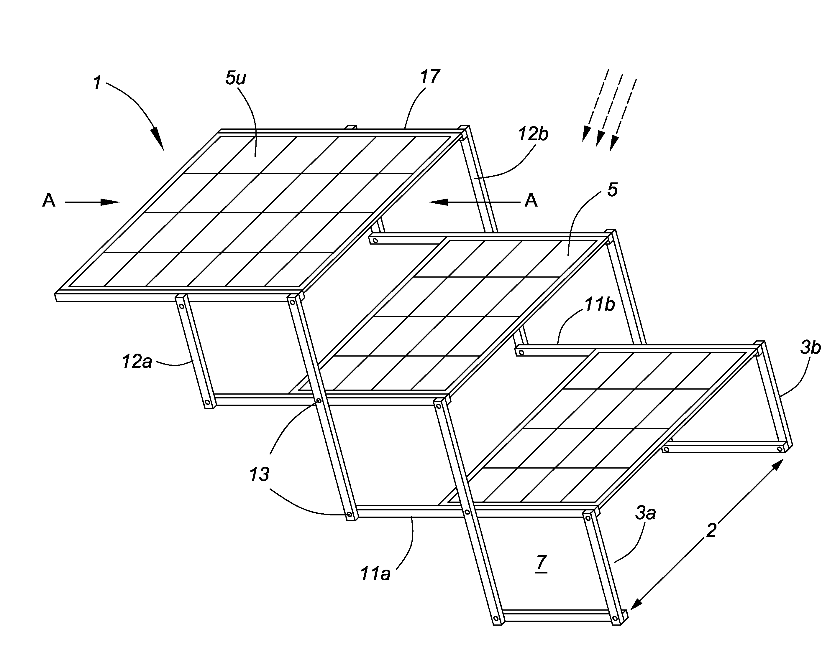
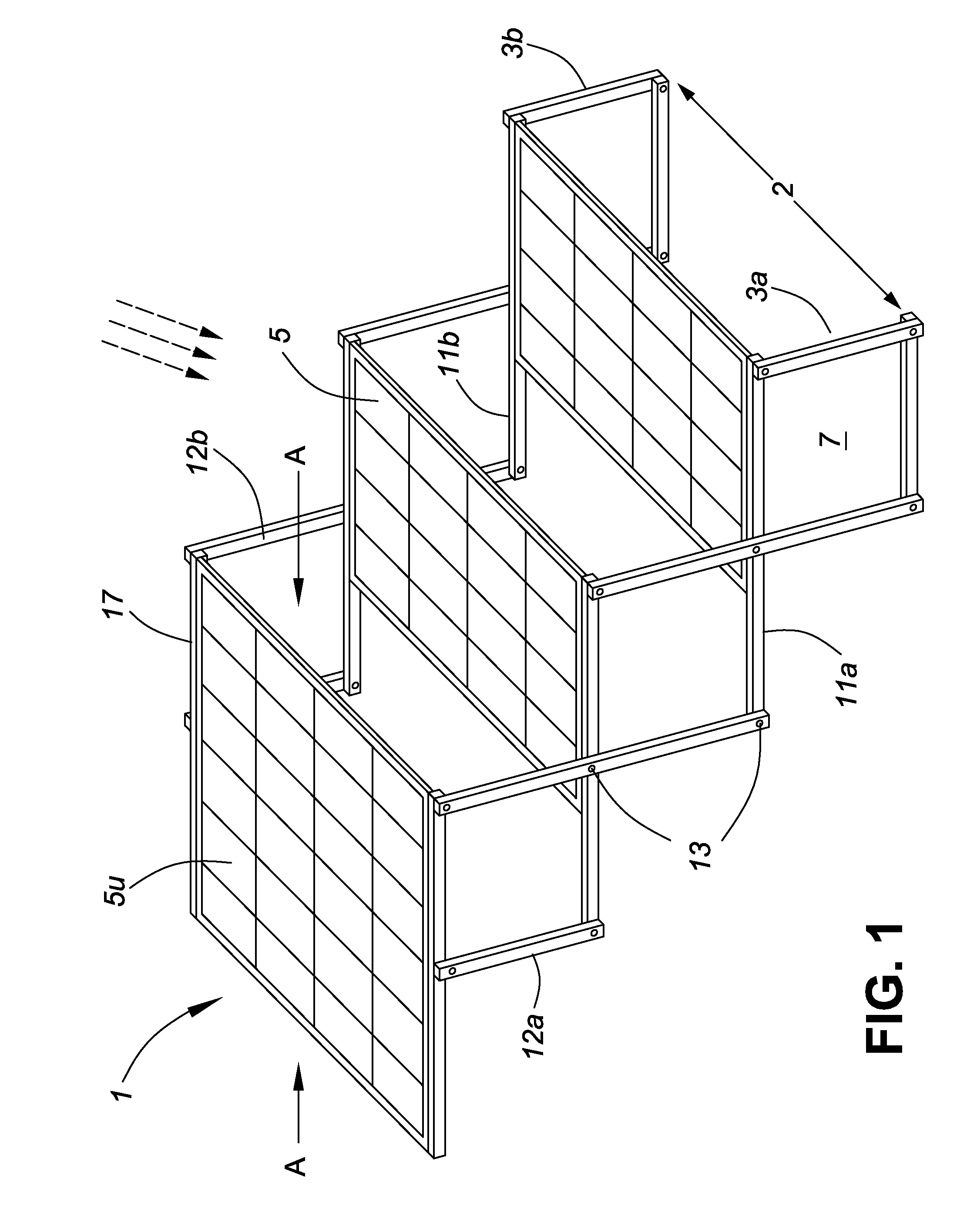
[0025]The first preferred embodiment of PV array of present invention is indicated generally at 1. It is shown in FIG. 1 in its deployed condition for a large solar elevation angle, such as midday in the summer. As can be seen, the solar array has a staircase-like form. A pair of laterally spaced pantographs 3a and 3b make up the collapsible support unit 2 for solar PV modules, which are indicated generally at 5. In this view three modules are shown by way of example. Each pantograph has the form of a set of interconnected rhombs 7 which are made by elongated arms 11 which support the solar PV modules, and by connecting arms or links 12, which are pivotally joined to each other by scissor linkages or pivots 13. In FIG. 1 by way of example each pantograph consists of three such rhombs. The pantographs are oriented approximately mirror symmetric to e...


PUM


Abstract

A deployable photovoltaic array comprising a plurality of photovoltaic modules attached to a collapsible support unit, where said support unit is made up of a pair of laterally spaced similar pantographs. Each pantograph has the form of a plurality of interconnected rhombs made by pivotally joined elongated arms. Two opposite sides of each solar module are attached to a pair of corresponding nearest parallel arms on the opposite sides of said pantographs. Said array in its deployed condition for large solar elevation angles acquires a characteristic staircase-like form. Angles of said rhombs may further be adjusted to achieve an optimal inclination of said solar modules with respect to the current direction to the sun. In the stowed configuration said array may be held in a protecting container, and is readily portable.

Description

CROSS-REFERENCE TO RELATED APPLICATIONS[0001]This application claims priority from U.S. provisional patent application Ser. No. 61 / 608,364 filed Mar. 8, 2012.TECHNICAL FIELD[0002]This invention generally relates to a solar radiation collection system, and more particularly to an array of photovoltaic (PV) modules mounted on a collapsible support unit.BACKGROUND OF THE INVENTION[0003]The potential permanent exhaustion of world natural resources calls for development of alternative sources of energy. Solar power provides an essentially inexhaustible source of energy. However, the intensity of solar radiation on earth is relatively low, and large areas are needed for solar harvesting systems in which sunlight is collected and converted into electricity, typically by photovoltaic (PV) generation means. These systems need rather large initial investments to be constructed, and must therefore run for longest possible time to make profit.[0004]The efficiency of PV cells is permanently grow...

Claims


Application Information

Patent Timeline
IPC IPC(8): H01L31/045
CPCH02S30/20H01L31/045F24S2025/012Y02E10/50Y02E60/10H01M10/613
Inventor RODIN, VADIMRODIN, LIUBOV
Owner RODIN VADIM
Why Eureka
Try Eureka