Cold plate with combined inclined impingement and ribbed channels

a cold plate and inclined impingement technology, applied in the field of cooling devices, can solve the problems of increasing the need for effective heat dissipation, increasing the amount of heat, and no straightforward extension of those principles for high heat flux in the smaller and more efficient electronic devices, and achieves the effect of increasing the local heat transfer ra

Active Publication Date: 2013-09-12
IBM CORP
View PDF11 Cites 35 Cited by
  • Summary
  • Abstract
  • Description
  • Claims
  • Application Information

AI Technical Summary

Benefits of technology

[0007]A heat transfer device is shown that includes a first enclosure that has at least one inlet port; a second enclosure that has a bottom plate and one or more dividing walls to establish a plurality of channels, at least one internal surface of each channel having a plurality of rib structures to create turbulence in a fluid flow; and a jet plate connecting the first enclosure and the second enclosure having a plurality of impinging jets that convey fluid from the first enclosure to the plurality of channels, said impinging jets being set at an angular deviation from normal to cause local acceleration of fluid and to increase a local heat transfer rate.

Problems solved by technology

Meeting that demand produces an increased amount of heat, and therefore also increases the need for effective heat dissipation.
While conventional cooling solutions have worked on the devices of the past, no straightforward extension of those principles has been found for high heat fluxes in the smaller and more efficient electronic devices that present fabrication technologies are capable of producing.
In particular, the air-cooled heatsinks of the past are ineffective in addressing the cooling needs of modern devices.
However, there are practical limitations to the efficiency of such devices when implemented at small scale.

Method used


Image

  • Cold plate with combined inclined impingement and ribbed channels
  • Cold plate with combined inclined impingement and ribbed channels
  • Cold plate with combined inclined impingement and ribbed channels

Examples


Embodiment Construction

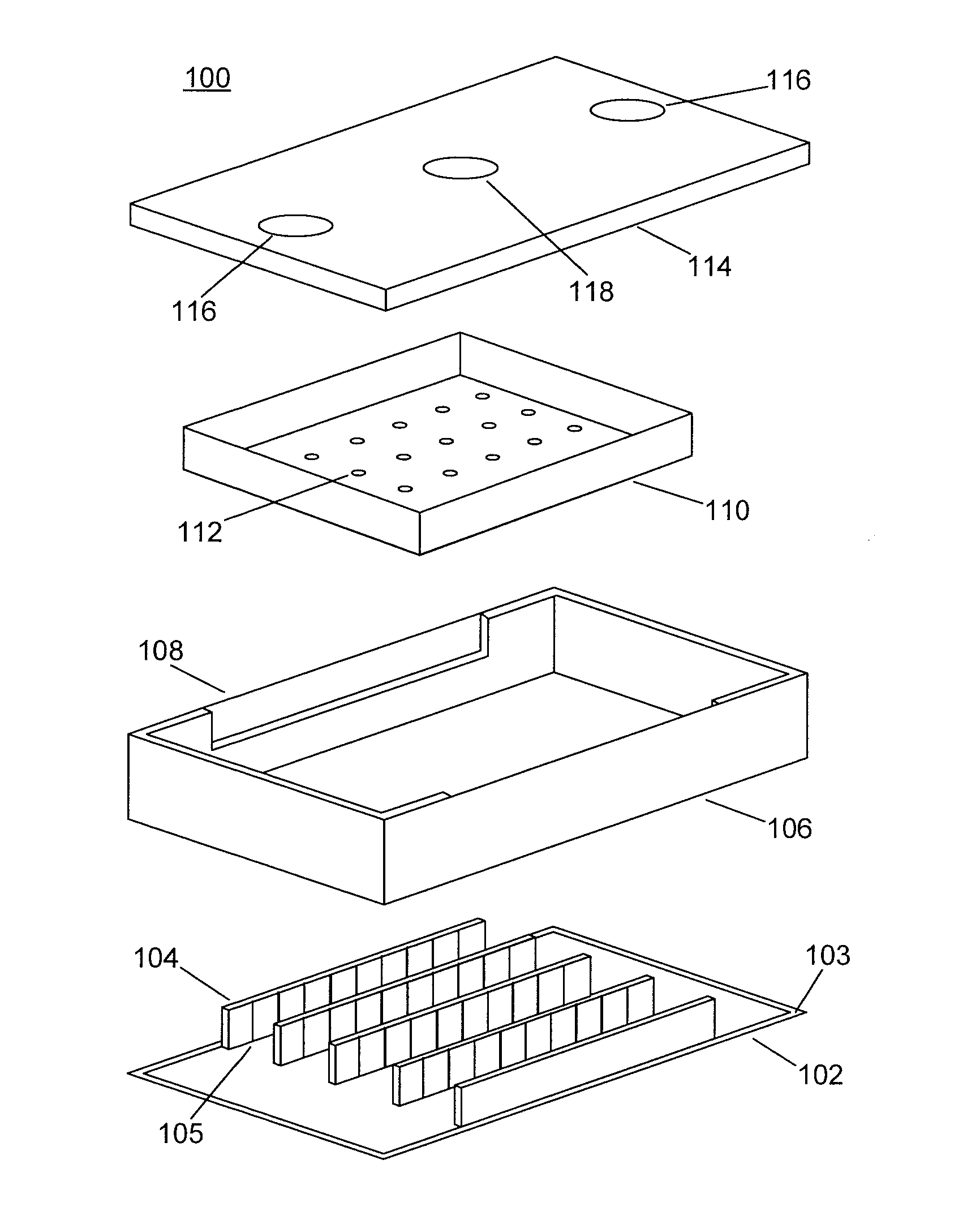
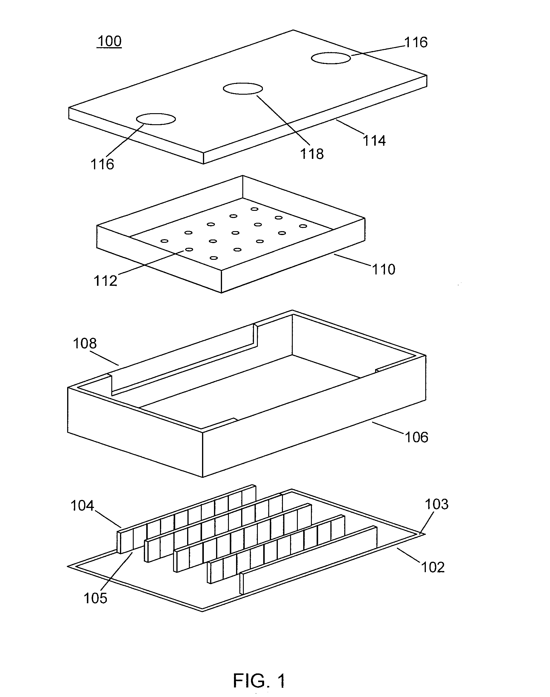
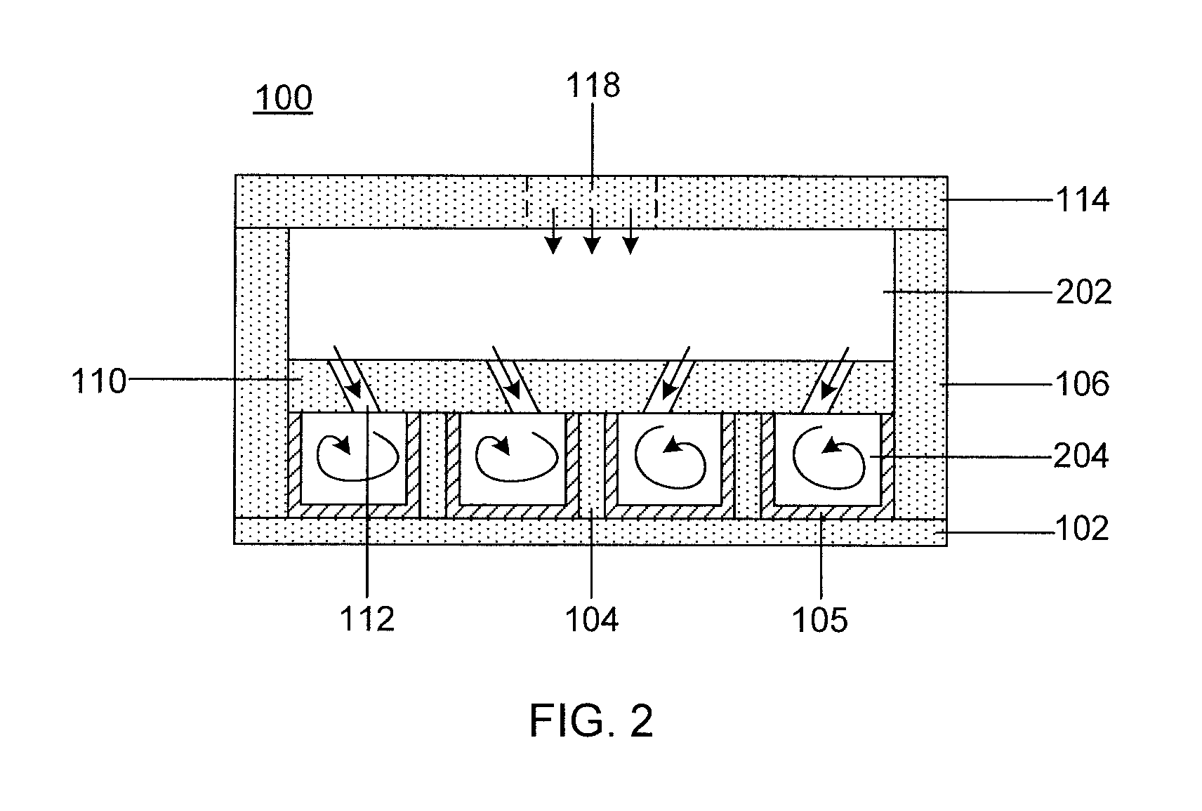
[0022]The present principles combine inclined impingement of coolant with ribbed cooling channels to produce a cold plate for high heat flux applications. The present embodiments use an array of impinging jets to provide high local heat transfer rates and, furthermore, provide an increased wetted surface area and increase flow turbulence along cooling channels with ribs, thereby increasing the overall heat transfer rates by exploiting efficiencies that result from particular kinds of coolant motion. When flow is turbulent, coolant particles exhibit additional transverse motion. This enhances the rate of energy and momentum exchange between coolant particles, thus increasing the heat transfer coefficient and increasing the cooling effect. This improves on conventional single-phase cooling systems, which do not concern themselves with coolant flow at such a minute level.

[0023]Although it is specifically contemplated that the present principles may be applied to fields of technology su...


PUM

PropertyMeasurementUnit
impingement anglesaaaaaaaaaa

Abstract

Heat transfer devices and methods for making the same that include a first enclosure having at least one inlet port; a second enclosure having a bottom plate and one or more dividing walls to establish channels, at least one internal surface of each channel having rib structures to create turbulence in a fluid flow; and a jet plate connecting the first enclosure and the second enclosure having impinging jets that convey fluid from the first enclosure to the channels, said impinging jets being set at an angular deviation from normal to cause local acceleration of fluid and to increase a local heat transfer rate.

Description

GOVERNMENT RIGHTS[0001]This invention was made with Government support under Contract No.: DE-EE0002894 (Department of Energy). The government has certain rights in this invention.BACKGROUND[0002]1. Technical Field[0003]The present invention relates to cooling and, more particularly, to cooling devices that use inclined impingement of coolant fluid into ribbed channels.[0004]2. Description of the Related Art[0005]The demand for increased power and performance in semiconductor devices grows constantly. Meeting that demand produces an increased amount of heat, and therefore also increases the need for effective heat dissipation. While conventional cooling solutions have worked on the devices of the past, no straightforward extension of those principles has been found for high heat fluxes in the smaller and more efficient electronic devices that present fabrication technologies are capable of producing. In particular, the air-cooled heatsinks of the past are ineffective in addressing t...

Claims


Application Information

Patent Timeline
Patent Type & Authority Applications(United States)
IPC IPC(8): F28F13/12B23P15/26
CPCH01L23/4735H01L2924/0002Y10T29/4935H01L2924/00Y10T29/49359H05K7/20263F28F13/02F28F3/02H01L23/467F28F2215/10H05K7/20218F28F3/048B23P15/26H05K7/20254
Inventor PARIDA, PRITISH R.
Owner IBM CORP
Why Eureka
Try Eureka