Remotely operated system for use in hydraulic fracturing of ground formations, and method of using same

a remote-operated system and hydraulic fracturing technology, applied in the direction of drilling pipes, drilling casings, borehole/well accessories, etc., can solve the problems of ineffective and unsafe manual operation of ground valves, damage to the well itself and the fracturing equipment, and well head rupture, etc., to reduce the velocity of slurry, maintain the effect of longevity and safe continuation of operations

Inactive Publication Date: 2013-09-12
LOOPER REED & MCGRAW P C
View PDF2 Cites 47 Cited by
  • Summary
  • Abstract
  • Description
  • Claims
  • Application Information

AI Technical Summary

Benefits of technology

[0019]Yet, another advantage of the present invention is that the accumulator's controls may be operated manually or may be programmed to operate and function automatically from a control office or anywhere in the field by reversibly remotely actuated a transmitter/receiver set of the type commonly used for opening and closing garage doors from a hand held unit.
[0020]According to one embodiment of the present disclosure, the system comprises a Zipper Manifold for selectively servicing two or more wells, said Zipper Manifold connecting the fracturing equipment with each of the servicing well head, wherein said Zipper Manifold comprises a flow-T connector, wherein the fracturing slurry reaches said flow-T connector at approximately 45 degree angle, thus reducing velocity of the slurry and an erosion of the valves positioned in each outlet of the flow-T connector and the downstream components, said system of valves comprising at least two (2) remotely operated ground valves disposed within the flow lines on both ends of the flow-T connector and at least two (2) manually operated ground valves positioned downstream of the at least two (2) remotely operated ground valves.
[0021]According to one embodiment of the present disclosure, the remotely controlled at least two (2) ground valves of the Zipper Manifold may be operated by a separate accumulator unit or, by the same accumulator unit as the at least three (3) ground valves discussed above. If the at least two (2) remotely controlled valves are operated by the separate accumulator unit, said accumulator is preferably positioned outside the Danger Zone.
[0022]Exemplary embodiments further include a method of fracturing subterranean formations, comprising: disposing at least three (3) ground valves within a flow lines, wherein said flow lines connect s source of

Problems solved by technology

However, the valves which are placed at the well head to form a well tree (Charismas Tree) are often not capable of containing such pressures, which may cause a blow-up or rupture of the well head, severe damage to the well itself and the fracturing equipment placed nearby.
The manually operated ground valves, however, have proven unsafe and inefficient for the reasons explained below.
First, in a blow-up of the well, the manually controlled valves are in a “Danger Zone,” an area of high probability of injury occurring due to the flying debris from the dismantling well.
If the field personnel are caught around the valves while attempting to manually stop the flow of the fracturing slurry between the stages of the fracturing operation, that person inevitably is exposed to a grave injury.
If the person is outside the Danger Zone at the time of ensuing blow-up, it will not be safe to walk up to the ground valves to manually turn the handweel of the valve in order to prevent further damage to the fracturing equipment.
The fluids introduced into the well are not only highly pressurized but are generally corrosive and abrasive because they are frequently laden with corrosive acids and abrasive propellants such as sharp sand, shale, coal or the like.
In addition to dangers related to manually controlled ground valves, the presently used in the industry ground valves suffer from a number of significant disadvantages due to the known condition called “bleeding back” during which the pressurized fracturing slurry backs up to the fracturing equipment and causes the ground valves to

Method used


Image

  • Remotely operated system for use in hydraulic fracturing of ground formations, and method of using same
  • Remotely operated system for use in hydraulic fracturing of ground formations, and method of using same
  • Remotely operated system for use in hydraulic fracturing of ground formations, and method of using same

Examples


Embodiment Construction

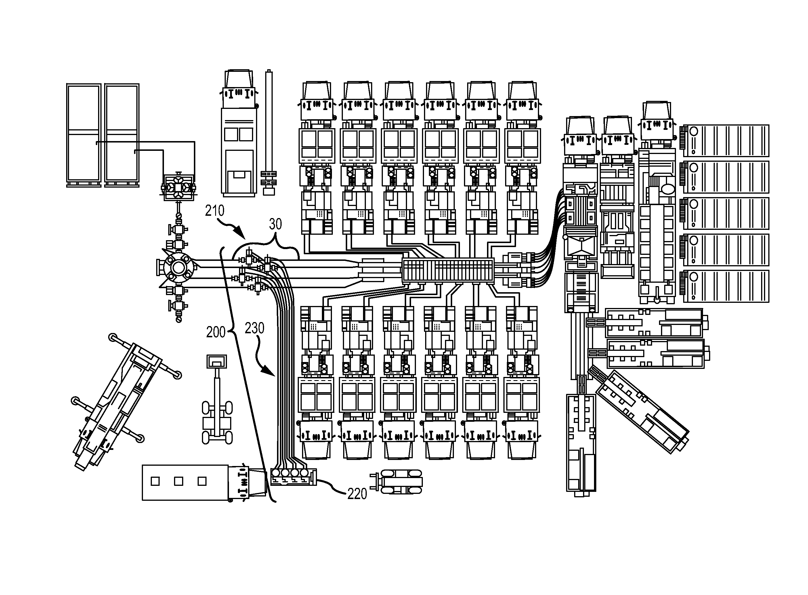
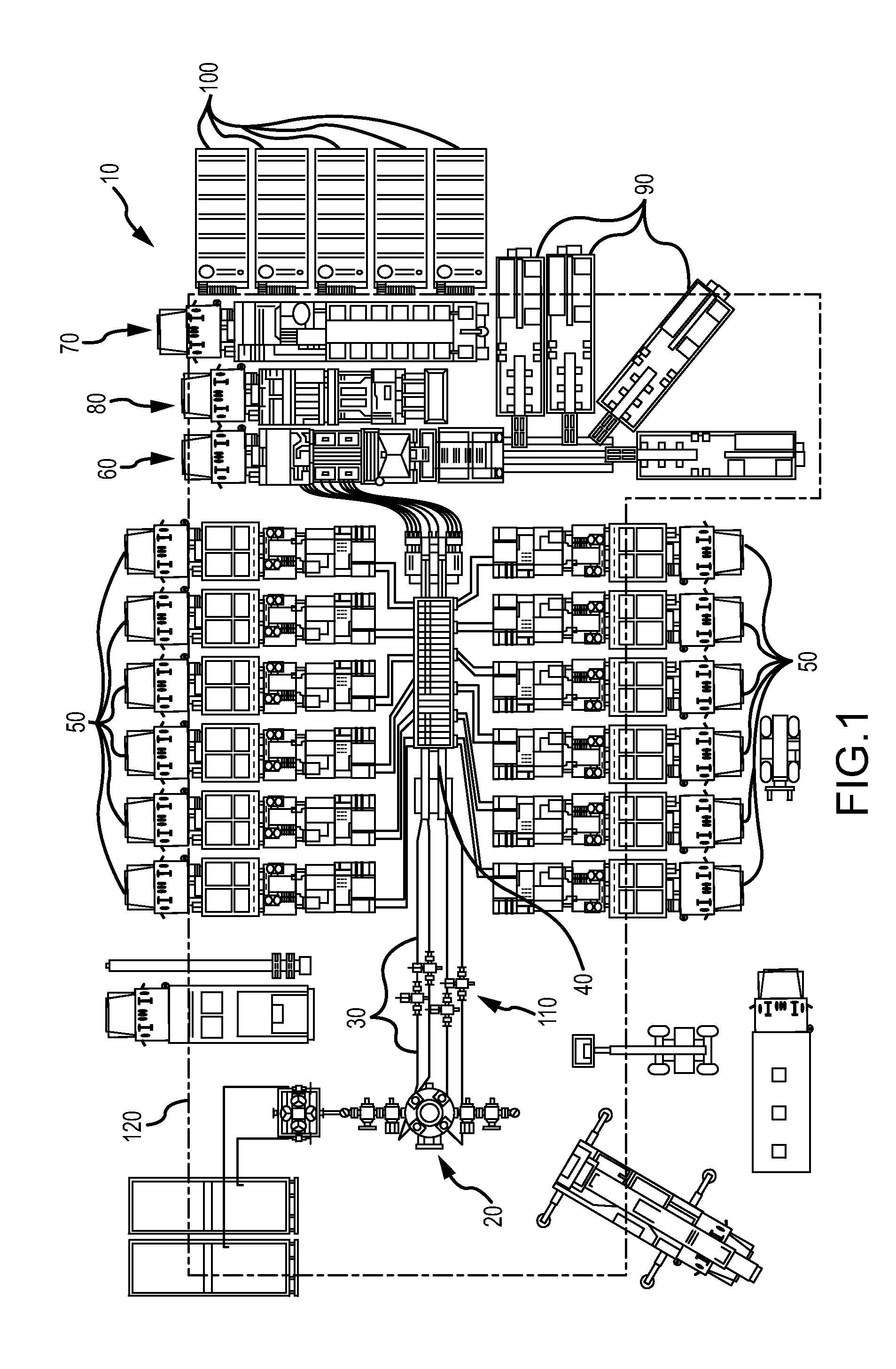
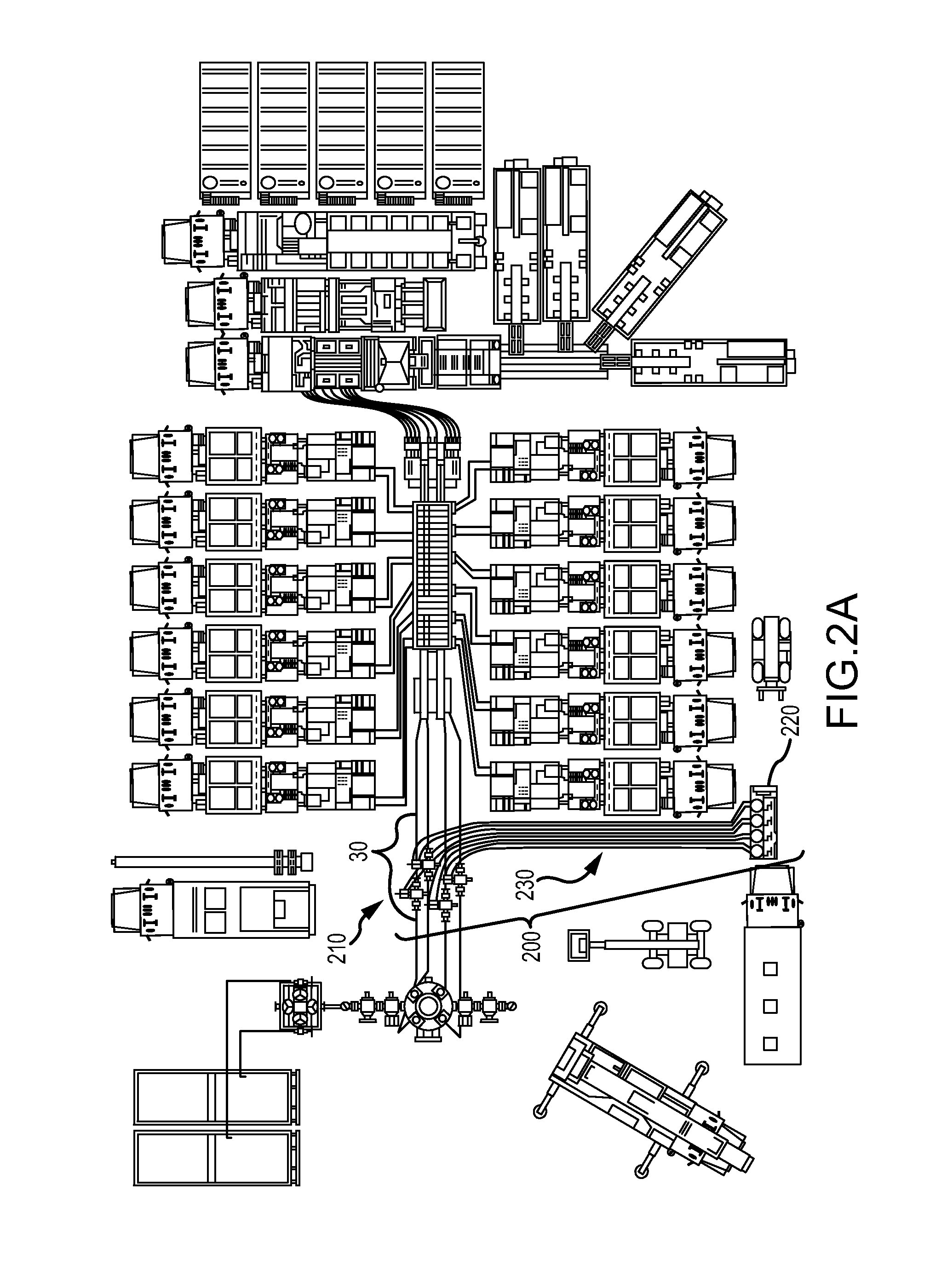
[0034]Referring now to the drawings, wherein like reference numbers are used herein to designate like elements throughout, the various views and embodiments of a remotely operated system and method of using same for the purpose of safely and cost-effectively conducting fracturing of the subterranean formations are illustrated and described, and other possible embodiments are described. The figures are not necessarily drawn to scale, and in some instances the drawings have been exaggerated and / or simplified in places for illustrative purposes only. One of ordinary skill in the art will appreciate the many possible applications and variations based on the following examples of possible embodiments. As used herein, the “present disclosure” refers to any one of the embodiments described herein, and any equivalents. Furthermore, reference to various aspects of the disclosure throughout this document does not mean that all claimed embodiments or methods must include the referenced aspects...


PUM


Abstract

The purpose of this invention is to improve on the safety and to allow more efficient production of subterranean formation during fracturing operations with a reduced down-time, minimal supervision and maintenance expense by utilizing remotely operated ground valves having metal-to-metal, gate and seat seal design operable to maintain a dual sided flow and pressure control. Use of a new 45-degree flow-T connector of a Zipper Manifold in combination with the system described is particularly useful for reducing erosion with proppant-laden fracturing fluid.

Description

CROSS-REFERENCE TO RELATED APPLICATIONS[0001]This U.S. Utility Application claims priority pursuant to 35 U.S.C. §119(e) to the following U.S. Provisional Patent Application, the specification of which is incorporated herein by reference for all purposes: U.S. Provisional Application Ser. No. 61 / 608,915, titled “Method and Processes for Improved Frac Drilling Operations,” filed Mar. 9, 2012, pending.TECHNICAL FIELD[0002]A remotely operated system for the purpose of safely and cost-effectively conducting hydraulic fracturing of ground formations and method of using same is disclosed. In particular, a system and method utilizing a remotely operated system of ground valves disposed between fracturing equipment and a well bore, is set forth.BACKGROUND OF THE INVENTION[0003]Induced hydraulic fracturing, commonly known as fracking is a technique used to release petroleum, natural gas, or other substances for extraction by utilizing pressurized fluid such as water, brine, foam or the like ...

Claims


Application Information

Patent Timeline
IPC IPC(8): E21B43/26
CPCE21B43/26E21B43/2607
Inventor DAVIDSON, ANDY LEE
Owner LOOPER REED & MCGRAW P C
Why Eureka
Try Eureka