Roller conveyor curve with round drive belts

Active Publication Date: 2013-09-12
INTERROLL HLDG
View PDF11 Cites 1 Cited by
  • Summary
  • Abstract
  • Description
  • Claims
  • Application Information

AI Technical Summary

Benefits of technology

[0042]The elongated hole can be formed as a through hole or as a blind hole. The bearing sites can have lateral boundary surfaces, which are parallel to each other at least over a portion of the elongated hole. During operation of such a roller conveyor, the axle ends of the conveyor rollers can move in the elongated bearing sites perpendicularly to the conveying plane, which is formed by the conveyor rollers. This enables a floating support on the drive belt running below the conveyor rollers, in which the conveyor rollers rest on the drive belt due to their weight or the weight of the transported goods. Due to the parallel lateral boundary surfaces, the axle ends or shaft ends of the conveyor rollers can be fixed in the bearing sites in the conveying direction. Since the elongated hole is closed at the top, the axle ends can be prevented from slipping out of the bearing sites. On the curve outer side, corresponding conveyor section bearing elements with bearing sites open at the top can be provided, so that the curve outer side axle ends can be placed into the curve outer side conveyor section bearing elements from above. The conveyor section bearing elements can be cut out o

Problems solved by technology

It has to be taken into account that only a few conveying means can be shortened to the desired length anyway and that the welding quality is difficult to ensure on the spot.
Too low a tension can lead to strong strand vibrations or to a skipping of the teeth on the tooth lock washer.
Too high forces cause a strong load on the bearings and the belt, and influence the gear components negatively by signs of wear.
Moreover, high forces, a strong rigidity of the belt, a plurality of belt redirections and/or the use of slide rails lead to a strong friction loss, to wear, and to an unnecessary energy loss.
For a large number of rollers, many transmission elements are required, so that friction and thus energy consumption and wear increase.
A drive by means of a driveshaft also requires many wraps of the transmission element, which leads to corresponding friction losses.
Moreover, the assembly of the transmission element is complex.
Ther

Method used


Image

  • Roller conveyor curve with round drive belts
  • Roller conveyor curve with round drive belts
  • Roller conveyor curve with round drive belts

Examples


Embodiment Construction

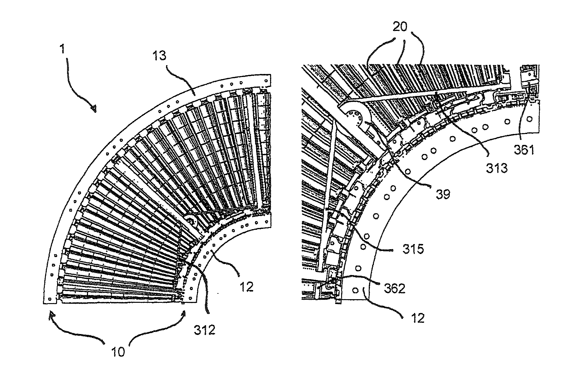
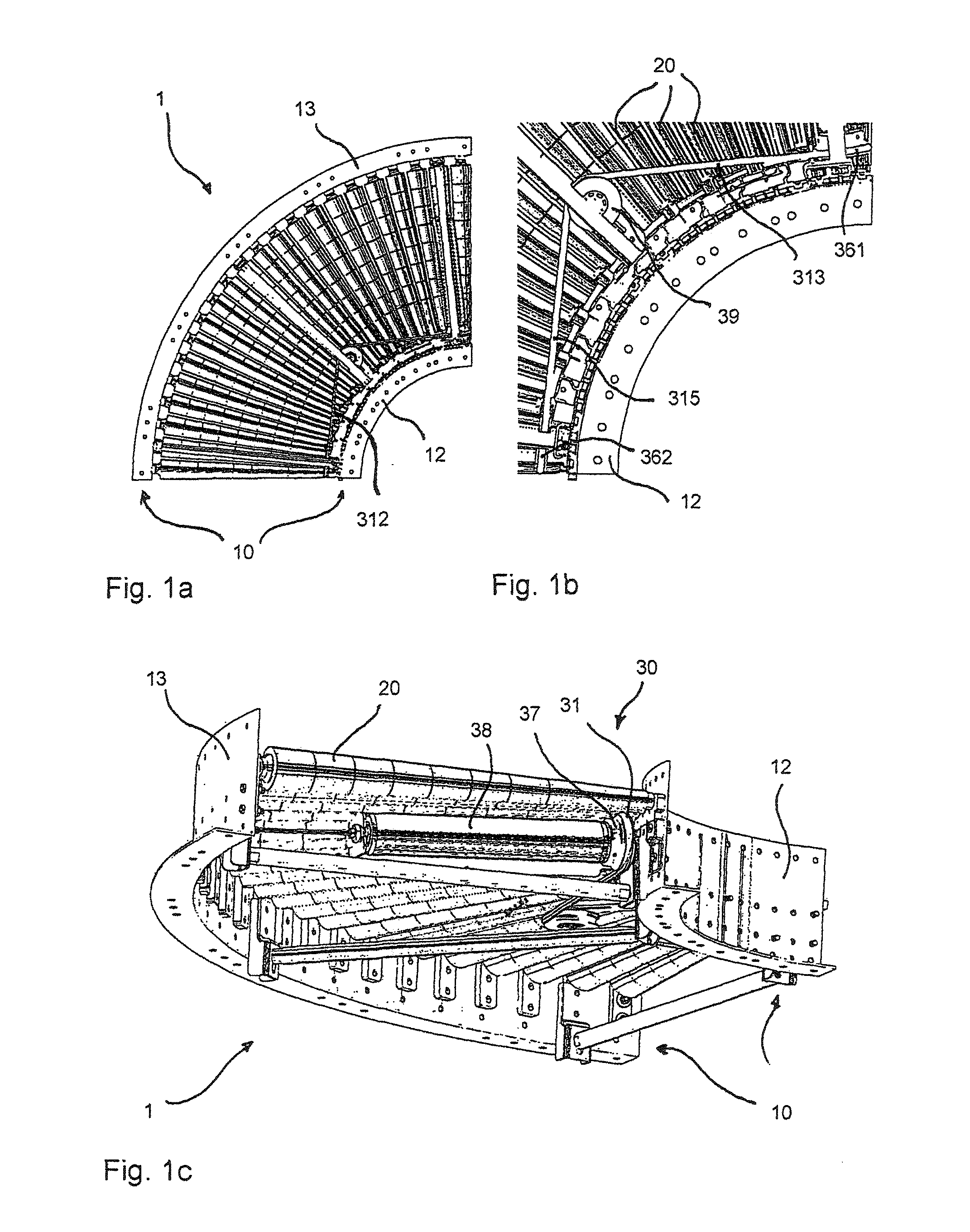
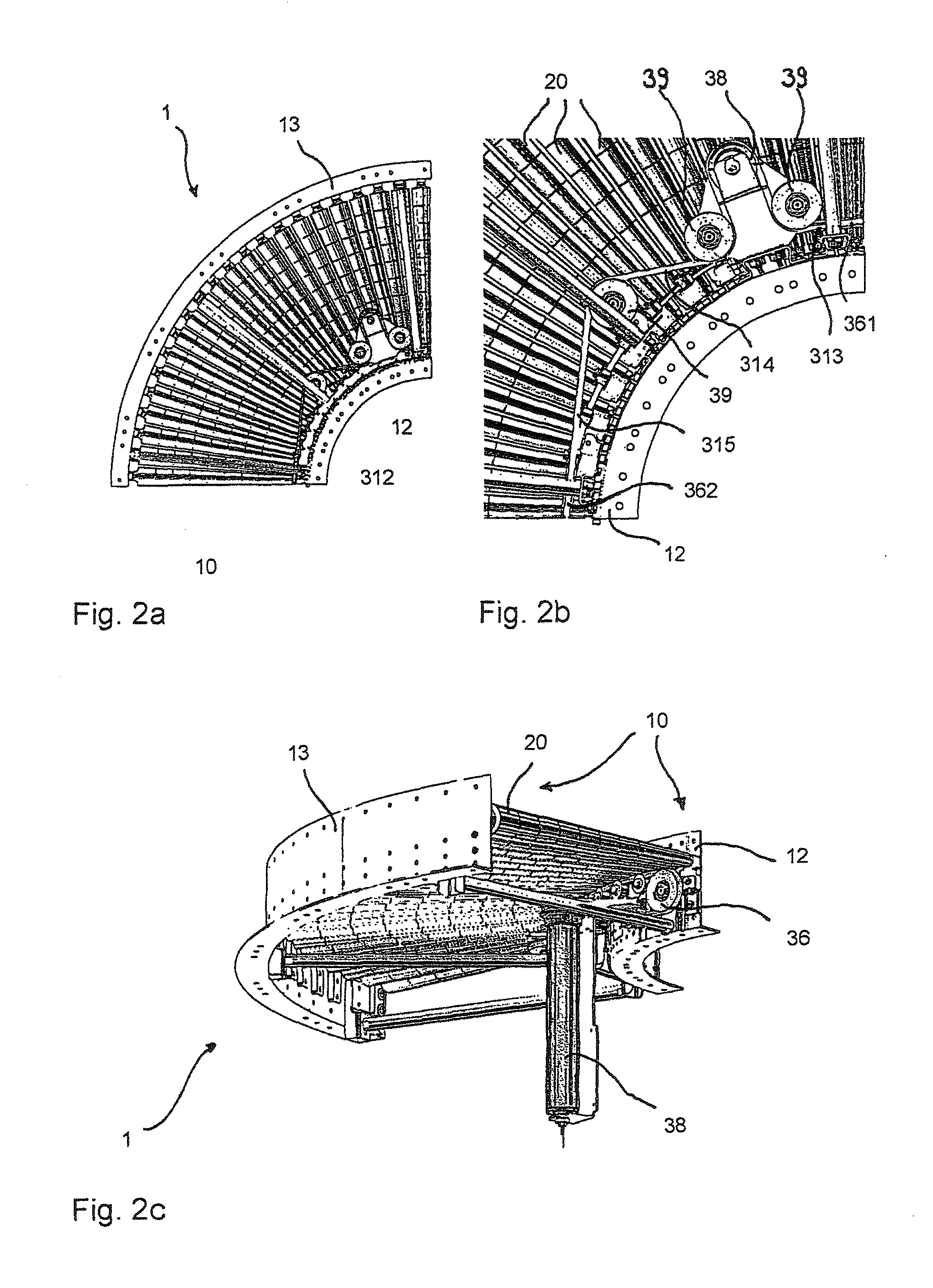
[0069]FIGS. 1a to 1c and FIGS. 2a to 2c show two different embodiments of a roller conveyor, which are each formed as a curved roller conveyor 1, the first embodiment comprising a lying drive motor 38 and the second embodiment comprising an upright drive motor 38. FIG. 1 and FIG. 2a each show the entire curve segment from the bottom side of the roller conveyor 1. FIGS. 1b and 2b each show an enlarged part in the same viewing direction. FIGS. 1c and 2c show the respective curve segment in an isometric view from obliquely below.

[0070]In the illustrated embodiment, the drive motor 38 is formed in the form of a driven conveyor roller having a driving roller 37 fixed to one axial end thereof. Driven conveyor rollers refer to conveyor rollers that are used as conveyor rollers in roller conveyors and that comprise a drive unit, in particular an electric motor, inside the cylindrical conveyor roller casing. This type of driven conveyor rollers is produced in large quantities and is thus ava...


PUM


Abstract

A curved roller conveyor (1) with a conveyor frame (10) and a plurality of conveyor rollers (20) rotatably supported on the conveyor frame (10), wherein the curved conveyor (1) has a drive system (30) with a drive belt (31) having a round cross-section, wherein several conveyor rollers (20) rest on the drive belt (31) in a floating manner.

Description

BACKGROUND[0001]1. Field of the Invention[0002]The present invention relates to a novel construction of driven roller tracks and to the components thereof.[0003]2. Description of the Related Art[0004]Thanks to many variants, roller tracks are the ideal way of transporting various goods.[0005]Among others, roller conveyors are also used to connect belt conveyors on a straight section or in curves. This often requires buffers capable of compensating for different clock cycles of machines. Here, accumulating conveyors with which an accumulating function can be obtained are sometimes used, which makes sense particularly for interlinking of machines.[0006]Among others, roller tracks can be used as light roller tracks or as standard roller conveyors.[0007]Light roller tracks, which are also referred to as minute roller conveyors, serve to transport small, light goods to be conveyed, in particular over short distances. Generally, light roller tracks transport general cargo of at most 15 kg...

Claims


Application Information

Patent Timeline
IPC IPC(8): B65G13/07
CPCB65G13/071B65G13/07B65G13/08B65G39/12B65G2812/02267
Inventor WOLTERS, THOMASDUDEK, SIEGMUND
Owner INTERROLL HLDG
Why Eureka
Try Eureka