Smartcard and Computer Quick Connect and Release System

Active Publication Date: 2013-09-12
IALL TECH
View PDF5 Cites 45 Cited by
  • Summary
  • Abstract
  • Description
  • Claims
  • Application Information

AI Technical Summary

Benefits of technology

[0017]Various aspects of the present invention make it possible for users to maintain possession of their smartcard. Some embodiments provide an improved disconnect between a smartcard unit and a computer unit. The smartcard unit could be defined as the smartcard itself, the smartcard and the smartcard holder, or the smartcard and

Problems solved by technology

However, there is then a risk that the user will move away from his or her computer, leaving the card in the card reader.
That both leaves the computer vulnerable to interference by an unauthorized user, and leaves the user without proper ID.
Since the smartcard is required for obtaining computer access, the computer may also monitor the presence of the smartcard in a smartcard reader so that when the smartcard is removed the computer access is limited or disabled.
A security risk is created if the computer is left unattended and accessible to an unauthorized user because a previous authorized user fails to remove his or her smartcard from the card reader before leaving the computer.
The design of smartcards, smartcard readers, and smartcard holders presents several problems that make this an undesirable method.
First, the smartcard reader may lack sufficient pressure to the smartcard's surface to supply enough frictional force to hold the smartcard in the smartcard reader against the retraction force from the reel.
Second, a non-axial force applied to the smartcard by the tether may cause the smartcard to become stuck in the smartcard reader.
That may result in the reader, and any attached equipment, being dragged out of position, or may result in either the smartcard or the entire reader coming

Method used


Image

  • Smartcard and Computer Quick Connect and Release System
  • Smartcard and Computer Quick Connect and Release System
  • Smartcard and Computer Quick Connect and Release System

Examples


Example

[0126]A better understanding of various features and advantages of the present methods and devices may be obtained by reference to the following detailed description of illustrative embodiments of the invention and accompanying drawings, in which like numerals designate like elements. Although these drawings depict embodiments of the contemplated methods and devices, they should not be construed as foreclosing alternative or equivalent embodiments apparent to those of ordinary skill in the subject art.

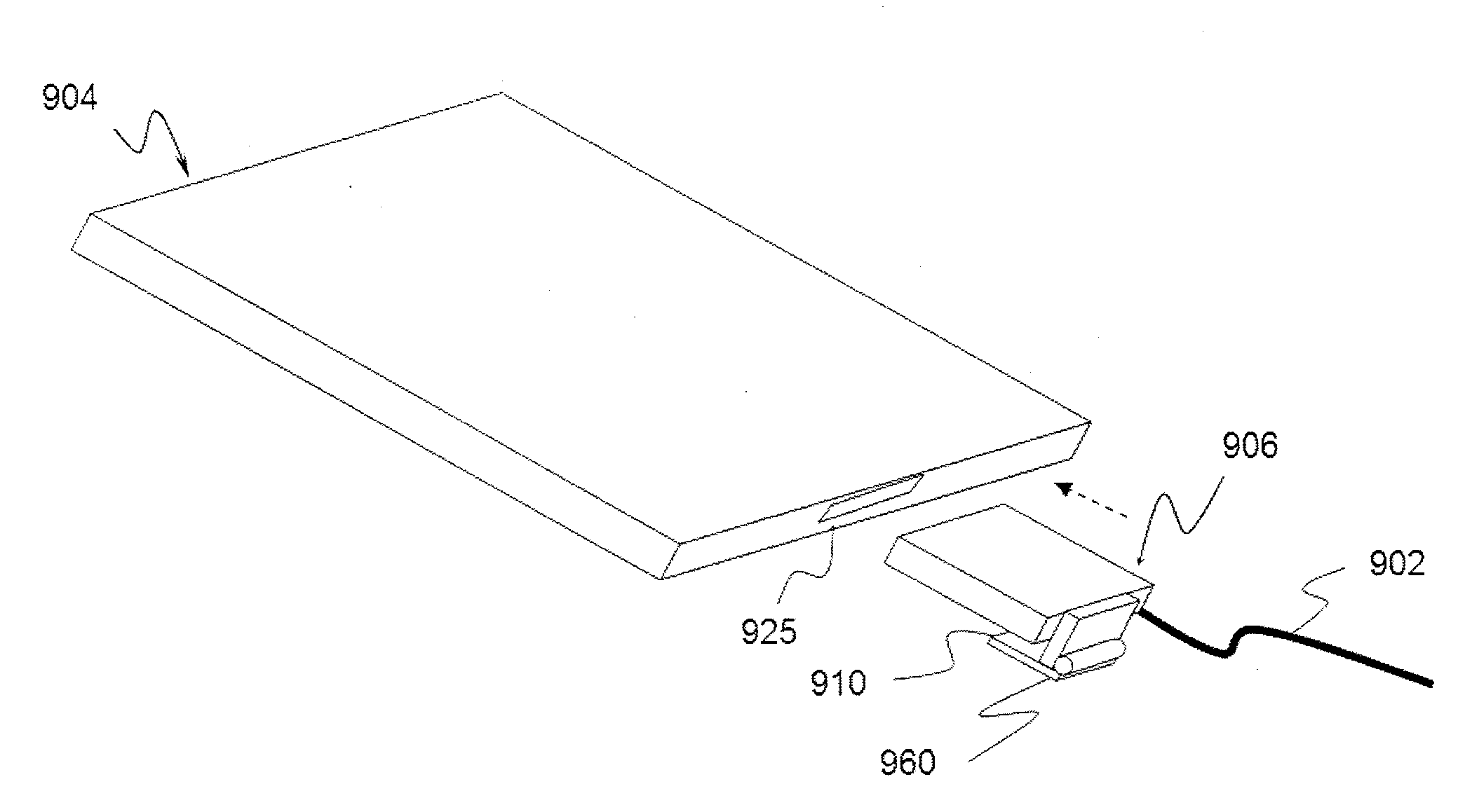
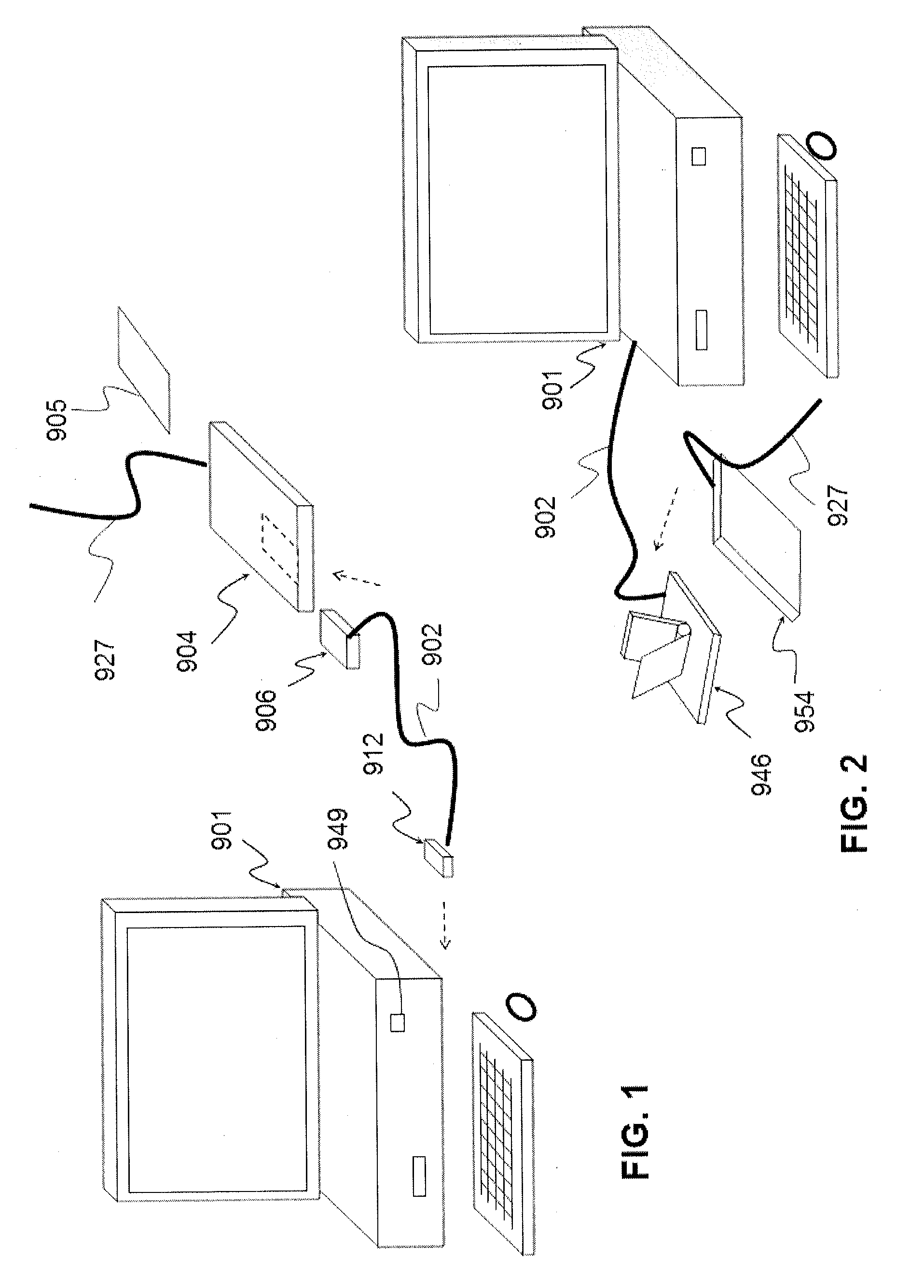
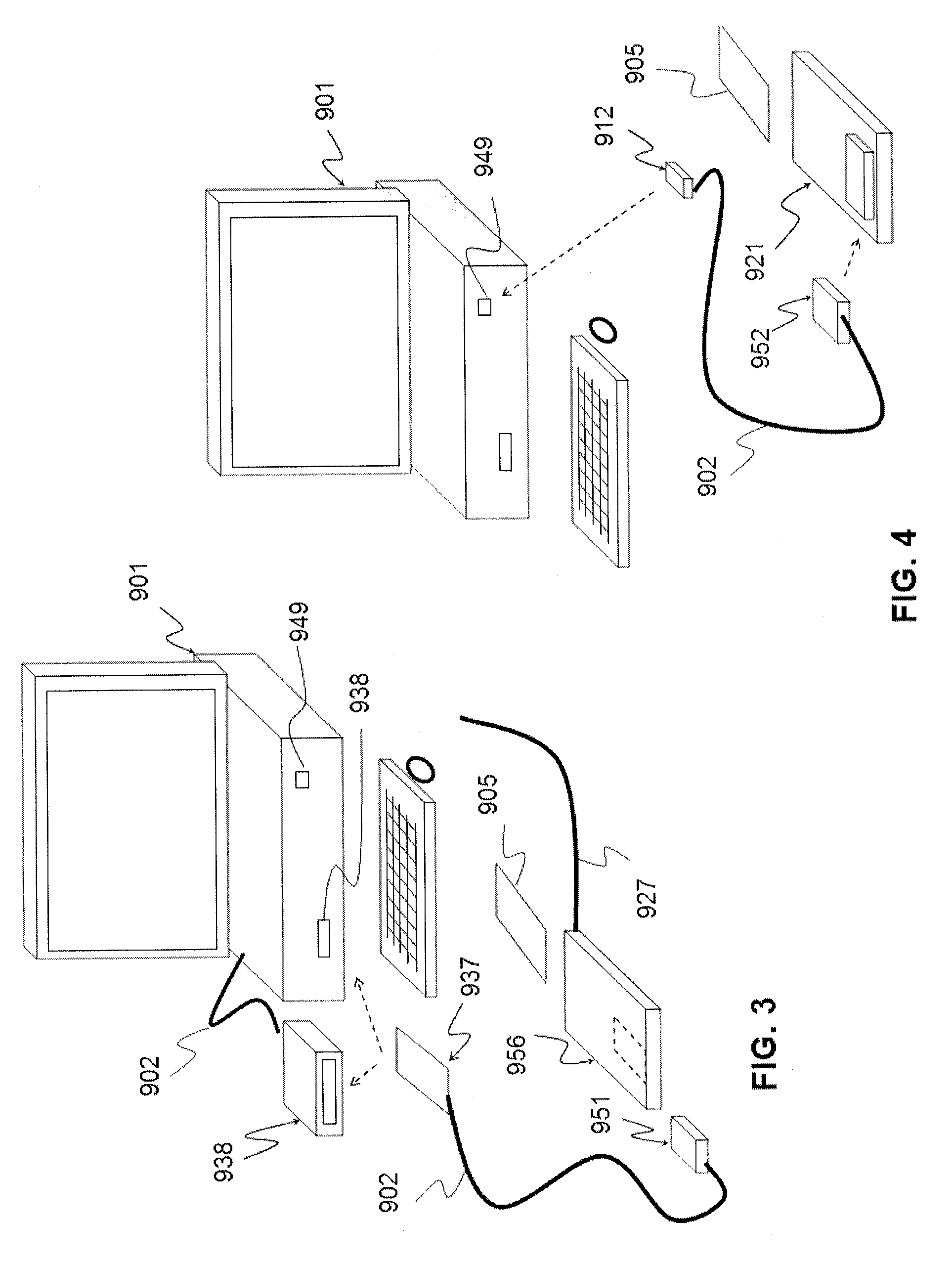
[0127]Referring to the drawings, and initially to FIG. 1, in one embodiment of a card holder and reader system according to an embodiment of the present invention, a smartcard 905 is inserted in use into a smartcard holder 904 to form a smartcard unit. The holder 904 is provided with a lanyard 927 by which the user can wear the holder 904, with the smartcard 905, round his or her neck. The smartcard 905 may then serve as a visible ID badge, and / or may be used as an access card for, for...


PUM


Abstract

A smartcard unit includes at least a smartcard and an attachment enabling the smartcard unit to be worn by a user. The smartcard is accessible to an external reader. A reader unit interfaces with the smartcard to enable an external computer to communicate with the smartcard. The smartcard unit or the reader unit has structure to align the reader unit relative to the smartcard unit in an alignment for communicative interfacing while the smartcard unit is being worn. The smartcard unit or the reader unit has a retainer to secure the reader unit in alignment relative to the smartcard so that the smartcard unit is reversibly separable from the reader unit without damage, in response to a force less than is necessary to detach or damage another part of said system, other than along a longitudinal axis of the smartcard or of a pair of components being separated.

Description

CROSS REFERENCE TO PRIOR APPLICATION[0001]This application claims benefit of U.S. Patent Application No. 61 / 607,119 by Burns, filed Mar. 6, 2012, for a “card holder and reader system for electronic smart card.” The whole content of that application is incorporated herein by reference as if explicitly set forth herein.FIELD OF DISCLOSURE[0002]The present disclosure relates to a card holder and reader system for a smartcard, and especially, a system including a card holder that is integrated with or operates in conjunction with a mating card reader to enable use of a smartcard configured for one or both of contact and contactless operation.BACKGROUND OF DISCLOSURE[0003]Electronic devices, such as a computer or computer system, commonly include an access terminal monitor, keyboard, and mouse, an operating system and or software, and may be connected to a network, including domain, or other control device for example, robotic or industrial controllers. An electronic device may also refe...

Claims


Application Information

Patent Timeline
IPC IPC(8): G06K7/015G06K7/06
CPCG06K7/0021G06K19/07741G06K19/005G06K19/07739G06K7/015G06K7/0056G06K7/10366G06K19/07743G06K19/07762
Inventor BURNS, CHRISTOPHER J.
Owner IALL TECH
Why Eureka
Try Eureka