Power Conversion and Control Systems and Methods for Solid-State Lighting

Active Publication Date: 2013-09-12
MCCUNE JR EARL W
View PDF4 Cites 7 Cited by
  • Summary
  • Abstract
  • Description
  • Claims
  • Application Information

AI Technical Summary

Benefits of technology

The solid-state lighting systems and methods of this patent offer a number of advantages over older systems. First, they have a simpler design and are less expensive to make. Second, they use an AC-DC converter which reduces the need for additional components and makes the system more energy efficient. Third, they are more reliable and have a longer lifetime. Fourth, they can be controlled individually, so if one or a few light-emitting devices fail, the entire system is not affected. Fifth, they can be dimmed to very low levels without flickering or premature light cut-off.

Problems solved by technology

Although the lighting performance characteristics of LEDs are superior to more conventional lighting technologies, widespread adoption of LED lighting has been slow.
The primary reason for the delay is that LED bulbs are expensive.
The high price of LED bulbs is significantly impacted by the costs involved in their manufacture, in particular the costs involved in manufacturing the power conversion circuitry needed to power the LED bulbs.
One well-known problem with the power conversion circuitry of the LED bulb 100 is that the bridge rectifier 102 and smoothing capacitor 104 present a nonlinear load to the AC mains.
A low power factor is highly undesirable since it results in reduced conversion efficiency, heating in the AC mains generator and distribution systems, and noise that can interfere with the performance of other equipment.
Unfortunately, introduction of the PFC pre-regulator 302 lowers energy efficiency, increases parts count and manufacturing costs, and makes it difficult to package the LED bulb 300 in a small form factor.
These high voltages tend to stress the LED bulb's 300 parts, leading to reliability problems.
The high voltages also pose safety concerns.
Yet another problem with existing LED bulbs relates to their inherent inability to be controlled by conventional dimmer switches.
Unfortunately, it does not provide an acceptable solution for dimming existing LED bulbs, like the prior art LED bulbs 100 and 300 in FIGS. 1 and 3.
However, LEDs are nonlinear devices and draw significantly less current than do incandescent bulbs.
Under these conditions, the TRIAC 408 can retrigger or turn OFF, resulting in annoying LED flickering, or the LED bulb prematurely turning OFF before reaching the desired dimming level.
The presence of the AC-DC power conversion circuitry between the AC power source and LEDs can also interfere with the ability of the TRIAC dimmer switch 400 to control the dimming of the LEDs.

Method used


Image

  • Power Conversion and Control Systems and Methods for Solid-State Lighting
  • Power Conversion and Control Systems and Methods for Solid-State Lighting
  • Power Conversion and Control Systems and Methods for Solid-State Lighting

Examples


Embodiment Construction

[0041]The exemplary embodiments of the present invention set forth below are described and illustrated in the context of solid-state lighting, particularly power conversion and control methods and systems for LED lighting. It is to be emphasized and understood, however, that the power conversion and control methods of the present invention are not limited to LED lighting applications; they are applicable to other lighting and non-lighting applications employing other types of loads, including solid-state (or non-solid-state) lighting devices other than LEDs, and devices that do not emit light but perform some other useful function.

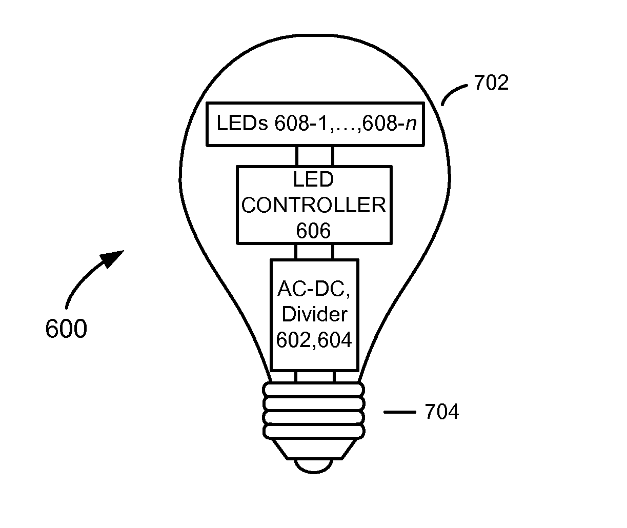
[0042]Referring to FIG. 6, there is shown a light-emitting diode (LED) bulb 600, according to an embodiment of the present invention. The LED bulb 600 comprises power conversion and control circuitry 601 that includes an alternating current to direct current (AC-DC) converter 602, a divider 604, and an LED controller 606; and LEDs 608-1, 608-2, . . . , 608...


PUM


Abstract

A power conversion and control system suitable for use with solid-state lighting and conventional TRIAC dimmer switching includes an alternating current to direct current (AC-DC) converter configured to convert AC power from the AC mains to DC power and a controller configured to control dimming of a light-emitting load depending on the magnitude of a distorted AC voltage from an external TRIAC dimmer switch relative to the magnitude of the DC voltage Vdc produced by the AC-DC converter. To prevent the TRIAC in the external TRIAC dimmer switch from turning off in situations where the AC-DC converter is disconnected from the AC mains or not drawing any current from the AC mains, the power conversion and control system may further include circuitry that maintains the current through the TRIAC above its minimum holding current.

Description

CROSS-REFERENCE TO RELATED APPLICATIONS[0001]The present application is a continuation-in-part of U.S. patent application Ser. No. 12 / 897,066, filed on Oct. 4, 2010, the disclosure of which is incorporated herein by reference in its entirety and for all purposes.FIELD OF THE INVENTION[0002]The present invention relates in general to electrical power conversion and control methods and systems and in particular to electrical power conversion and control methods and systems for solid-state lighting, such as, for example, light-emitting diode (LED) lighting.BACKGROUND OF THE INVENTION[0003]Due to their high efficiency and durability, light-emitting diodes (LEDs) are desirable candidates for providing general lighting in homes, offices and other environments. Whereas conventional incandescent lamps are only about 3% efficient, LEDs have efficiencies of 30% or higher. LED lifetimes are also over 20 times longer than incandescent lamps and over 5 times longer than compact fluorescent lamps...

Claims


Application Information

Patent Timeline
IPC IPC(8): H05B33/08H05B44/00
CPCH05B33/0815H05B45/355H05B45/375H05B47/10
Inventor MCCUNE, JR., EARL W.
Owner MCCUNE JR EARL W
Why Eureka
Try Eureka