Spindle positioning device

a positioning device and spindle technology, applied in the direction of instrumentation, electric programme control, program control, etc., can solve the problems of inability to perform positioning in the shortest time, and certain amount of time is required to perform calculation

Active Publication Date: 2013-09-12
OKUMA CORP
View PDF4 Cites 9 Cited by
  • Summary
  • Abstract
  • Description
  • Claims
  • Application Information

AI Technical Summary

Benefits of technology

[0017]By obtaining the maximum braking acceleration and the stop control start speed beforehand, it is possible to start the stop control immediately.
[0019]As described above, by employing a spindle positioning device for positioning a spindle at a desired rotational position according to the present invention, it is possible to position the spindle at a desired rotational position without overshoot, and quickly.

Problems solved by technology

However, the acceleration command “as” is calculated only when the rotational speed is less than or equal to the spindle motor base rotational speed, and a certain amount of time is necessary to perform the calculation.
Therefore, there is a problem in that positioning cannot be performed in the shortest time.

Method used


Image

  • Spindle positioning device
  • Spindle positioning device
  • Spindle positioning device

Examples


Embodiment Construction

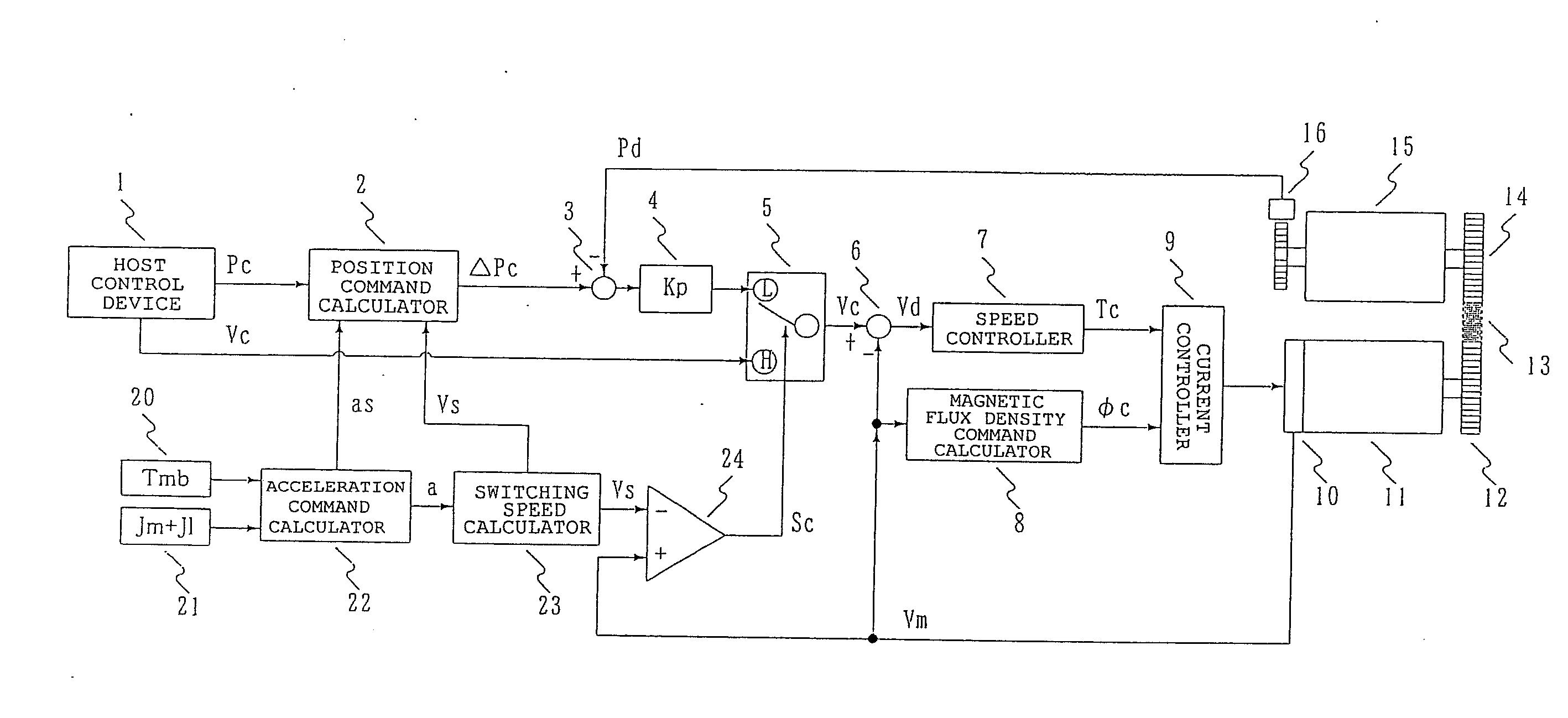
[0025]Embodiments of the present invention will be described below. The same elements as those of the related art example are denoted by the same reference numerals, and their description will not be repeated here. FIG. 3 shows a control block diagram of the present invention. An acceleration command calculator 22 calculates an acceleration a max using the following equation (4) based on an output torque Tmb [Nm] of the spindle motor which is applied when the rotational speed is less than or equal to abase rotational speed, and an inertia of the overall spindle, Jm+Jl, which is a sum of an inertia Jm of the spindle motor and an inertia Jl of the spindle including a chuck and a workpiece. The acceleration a max is output as an acceleration command “as” to the position command calculator 2 and a switching speed calculator 23. The inertia Jm+Jl of the overall spindle is an overall inertia of the spindle and a structure which rotates together with the spindle, and corresponds to a load ...


PUM


Abstract

An acceleration command calculator 22 calculates an acceleration command “as” based on an output torque Tmb of the spindle motor applied when the rotational speed is less than or equal to a base rotational speed and an inertia Jm+Jl of the overall spindle. A switching speed calculator 23 calculates a control mode switching speed Vs based on the acceleration command “as”. A control mode switching switch 5 switches from a speed control mode to a position control mode when the motor speed Vm becomes less than or equal to the control mode switching speed Vs, to stop the spindle at a desired rotational position. The control mode switching speed Vs may be a value calculated using the following equation:Vs=60×(amax×0.5)1 / 2,where a maximum acceleration that can be achieved at this time is represented by a max.

Description

CROSS-REFERENCE TO RELATED APPLICATION(S)[0001]This application claims priority to Japanese Patent Application No. 2012-049211, filed on Mar. 6, 2012, which is incorporated herein by reference in its entirety.BACKGROUND[0002]1. Technical Field[0003]The present invention relates to a positioning device for causing a spindle of a machine tool to stop at a desired position.[0004]2. Related Art[0005]With regard to positioning techniques for positioning and stopping a rotating spindle motor, it is desired that positioning be performed quickly and without overshoot. For such techniques, various attempts have heretofore been made.[0006]FIG. 1 shows a block diagram of a typical spindle positioning device. A spindle 15 is driven to rotate by a spindle motor 11 via a transmission mechanism 12 to 14 including a gear and a belt. A speed detector 10 detects a speed of the spindle motor 11, and outputs a speed detection value Vm [min−1]. A subtractor 6 uses the speed detection value Vm as a speed...

Claims


Application Information

Patent Timeline
Patent Type & Authority Applications(United States)
IPC IPC(8): H02P23/00B23Q15/08G05B19/416
CPCH02P23/0004H02P23/005G05D1/00G05B19/416G05B2219/42104G05B2219/43064G05B2219/43114H02P23/18G05B19/00
Inventor SHIBATA, TOMOHIROKAMEYAMA, TOMOHISA
Owner OKUMA CORP
Why Eureka
Try Eureka