Optical sensor and image forming device

an image forming device and optical sensor technology, applied in the direction of optical radiation measurement, instruments, polarisation-affecting properties, etc., can solve the problems of color irregularity, user inconvenience, and difficulty in obtaining images with optimal image quality, so as to achieve the effect of not increasing the cost of the device and the siz

Inactive Publication Date: 2013-09-12
RICOH KK
View PDF2 Cites 15 Cited by
  • Summary
  • Abstract
  • Description
  • Claims
  • Application Information

AI Technical Summary

Benefits of technology

[0016]In one aspect, the present disclosure provides an optical sensor which is capable of identifying a kind of a sheet finely without increasing the device cost and the size.

Problems solved by technology

In other words, unless appropriate fixing conditions are used for the kind of printing sheets, color irregularity will arise.
For this reason, there has been an inconvenience that the user has to be familiar with the knowledge for identifying the kind of the printing sheet used and for inputting the setting items of the print job according to the kind of the sheet manually.
If inappropriate setting items for the kind are input, it is difficult to obtain an image with the optimal image quality.
However, it is difficult for the image forming devices according to the related art to identify a kind of a sheet finely without increasing the device cost and the size.

Method used


Image

  • Optical sensor and image forming device
  • Optical sensor and image forming device
  • Optical sensor and image forming device

Examples


Embodiment Construction

[0054]A description will be given of embodiments of the present disclosure with reference to the accompanying drawings.

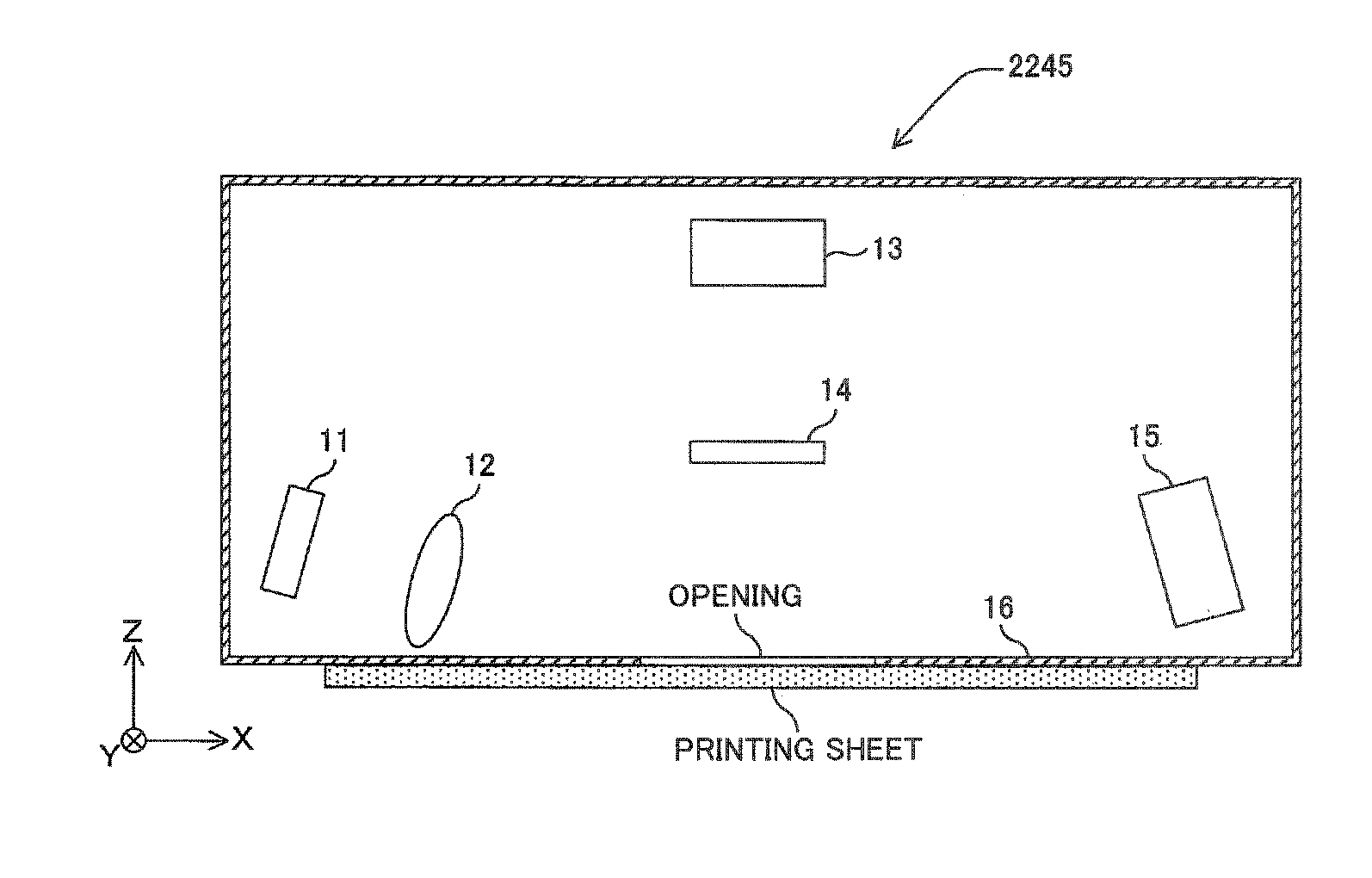
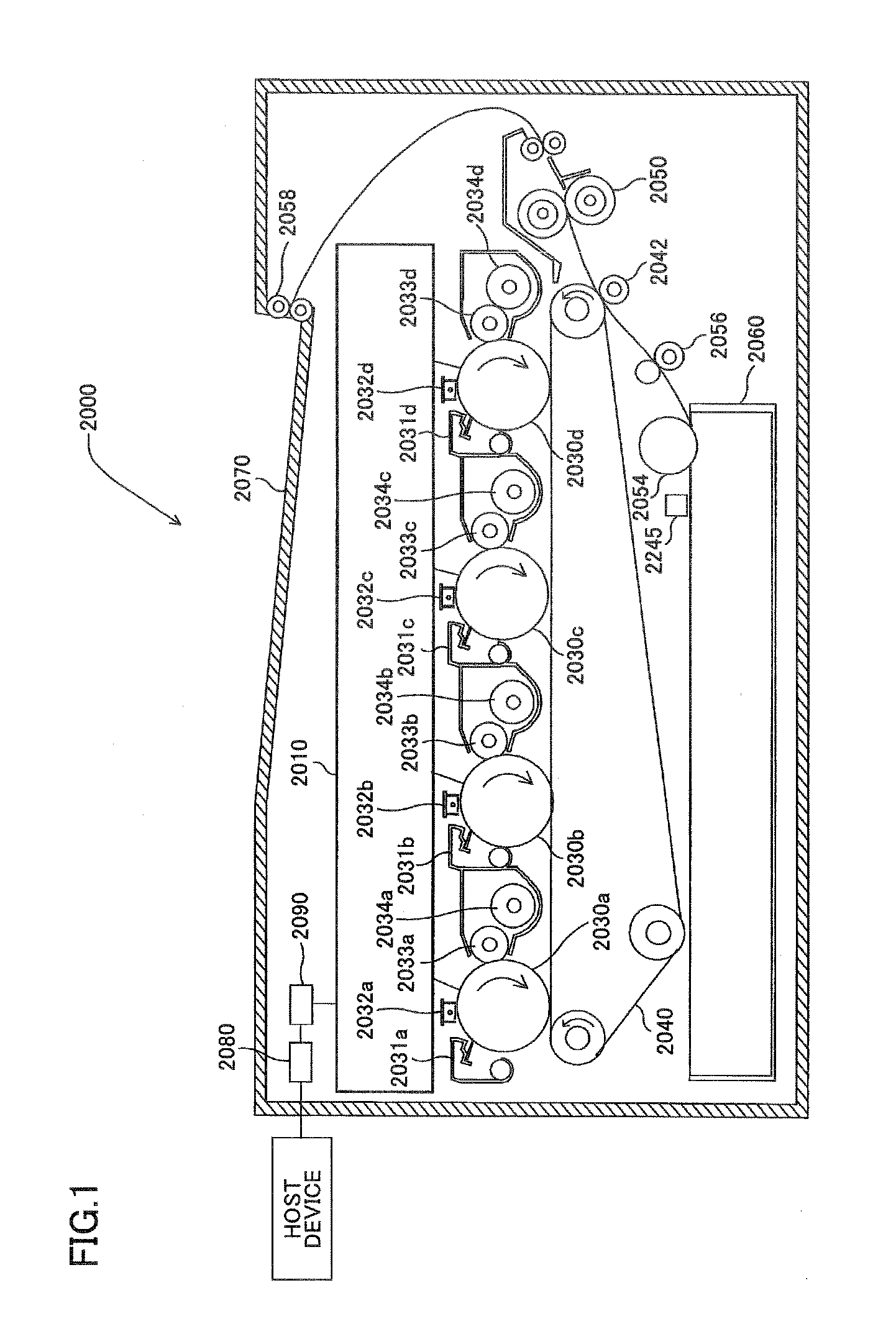
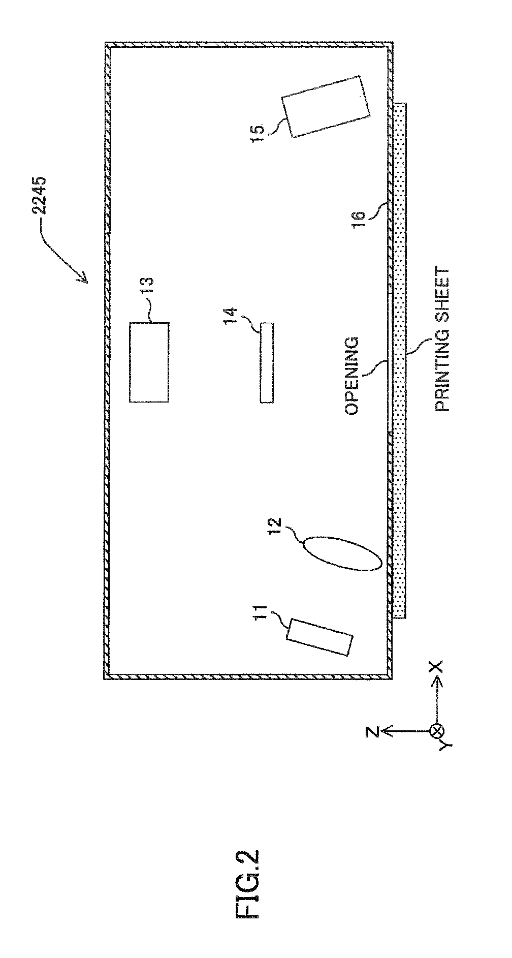
[0055]An embodiment of the present disclosure will be described with reference to FIGS. 1 to 14. FIG. 1 shows the outline composition of a color printer 2000 according to the present embodiment.

[0056]The color printer 2000 of the present embodiment is a tandem-type multi-color printer in which images of four colors (black, cyan, magenta, yellow) are superimposed so that a full-color image is formed. This color printer generally includes an optical scanning device 2010, four photoconductor drums 2030a, 2030b, 2030c, 2030d, four cleaning units 2031a, 2031b, 2031c, 2031d, four charging units 2032a, 2032b, 2032c, 2032d, four developing rollers 2033a, 2033b, 2033c, 2033d, four drive rollers 2034a, 2034b, 2034c, 2034d, a transfer belt 2040, a transfer roller 2042, a fixing unit 2050, a feed roller 2054, a delivery roller 2058, a sheet feed tray 2060, a sheet output tray 2...


PUM

PropertyMeasurementUnit
angleaaaaaaaaaa
incident angleaaaaaaaaaa
angle φ1aaaaaaaaaa

Abstract

An optical sensor includes: a light emission module to emit a linearly polarized light beam having a first polarizing direction to a surface of an object in an incident direction inclined relative to a direction of a normal to the surface; a first photodetector module including a first photodetector disposed within a plane of incidence of the surface in an optical path inclined relative to an optical path of a light beam emitted from the light emission module and regularly reflected on the surface; and a second photodetector module including an optical element disposed within the plane of incidence of the surface in an optical path of a diffused reflection light beam from the surface to separate a linearly polarized light beam having a second polarizing direction perpendicular to the first polarizing direction, and a second photodetector to receive the light beam separated by the optical element.

Description

BACKGROUND OF THE INVENTION[0001]1. Field of the Invention[0002]The present disclosure generally relates to optical sensors and image forming devices, and more particularly to an optical sensor adapted for identifying a kind of a sheet, and an image forming device including the optical sensor.[0003]2. Description of the Related Art[0004]In image forming devices, such as digital copiers and laser printers, a toner image is transferred to a surface of a print medium, which is represented by a printing sheet, and the toner image is fixed by heating and pressurizing in predetermined conditions so that an image is formed. One of important factors that must be taken into consideration in image formation is the fixing conditions, such as the heating amount or pressure at the time of the fixing. In order to perform image formation with high quality, it is necessary to set up the fixing conditions individually according to the print media.[0005]The image quality on printing sheets is greatly...

Claims


Application Information

Patent Timeline
Patent Type & Authority Applications(United States)
IPC IPC(8): G01N21/21
CPCG01N21/21
Inventor ISHII, TOSHIHIROOBA, YOSHIHIROHOSHI, FUMIKAZUADACHI, KAZUHIKOSUGAWARA, SATORU
Owner RICOH KK
Why Eureka
Try Eureka