Light emitting device, and illumination apparatus and luminaire using same

a technology illumination apparatus, which is applied in the direction of semiconductor devices for light sources, lighting and heating apparatus, light source combinations, etc., can solve the problems of difficult post-correction on the chromaticity of illumination light of light emitting devices, and achieve the effect of easy correction of the chromaticity and the chromaticity of ligh

Inactive Publication Date: 2013-09-12
PANASONIC INTELLECTUAL PROPERTY MANAGEMENT CO LTD
View PDF9 Cites 40 Cited by
  • Summary
  • Abstract
  • Description
  • Claims
  • Application Information

AI Technical Summary

Benefits of technology

[0007]The multiple kinds of light emission units may include a red light emission unit that emits red light, a green light emission unit that emits green light, and a blue light emission unit that emits blue light, and be grouped to obtain a white light by mixing lights emitted from the red light emission unit, the green light emission unit and the blue light emission unit, and the correction phosphor may correct a chromaticity of the white light emitted from each group to a single predetermined chromaticity.
[0008]Preferably, the correction phosphor corrects a chromaticity of the white light obtained when the solid state light emitting elements are driven with a rated output by the driver, to a desired chromaticity.
[0012]With the above configuration, the cover member has the correction phosphor which corrects the chromaticity of the light obtained by mixing the lights emitted from the multiple kinds of light emission units, so that it is possible to easily correct the chromaticity of the light obtained by mixing the light emitted from the light emission units through the cover member to obtain the illuminating light with the desired chromaticity.

Problems solved by technology

However, if the light emission unit and the light transmitting cover are formed integrally, a post-correction on the chromaticity of illumination light of the light emitting device becomes more difficult.

Method used


Image

  • Light emitting device, and illumination apparatus and luminaire using same
  • Light emitting device, and illumination apparatus and luminaire using same
  • Light emitting device, and illumination apparatus and luminaire using same

Examples


Embodiment Construction

[0021]Hereinafter, embodiments of the present invention will be described with reference to the accompanying drawings which form a part hereof. Throughout the specification and drawings, like reference numerals will be given to like parts having substantially the same function and configuration, and a redundant description thereof will be omitted.

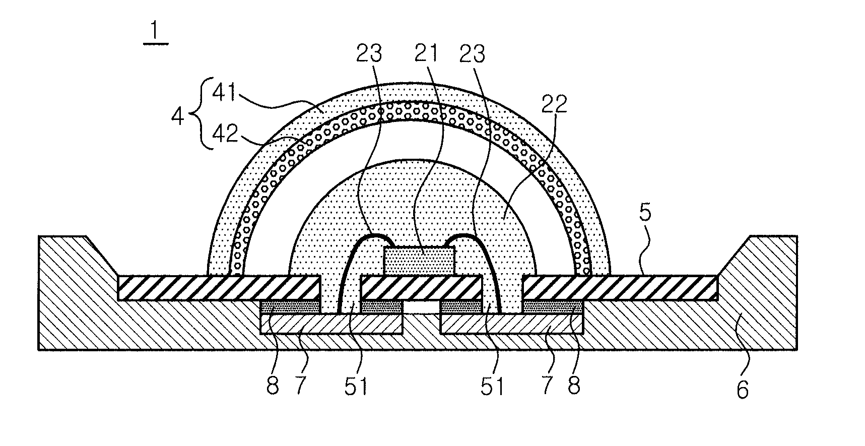
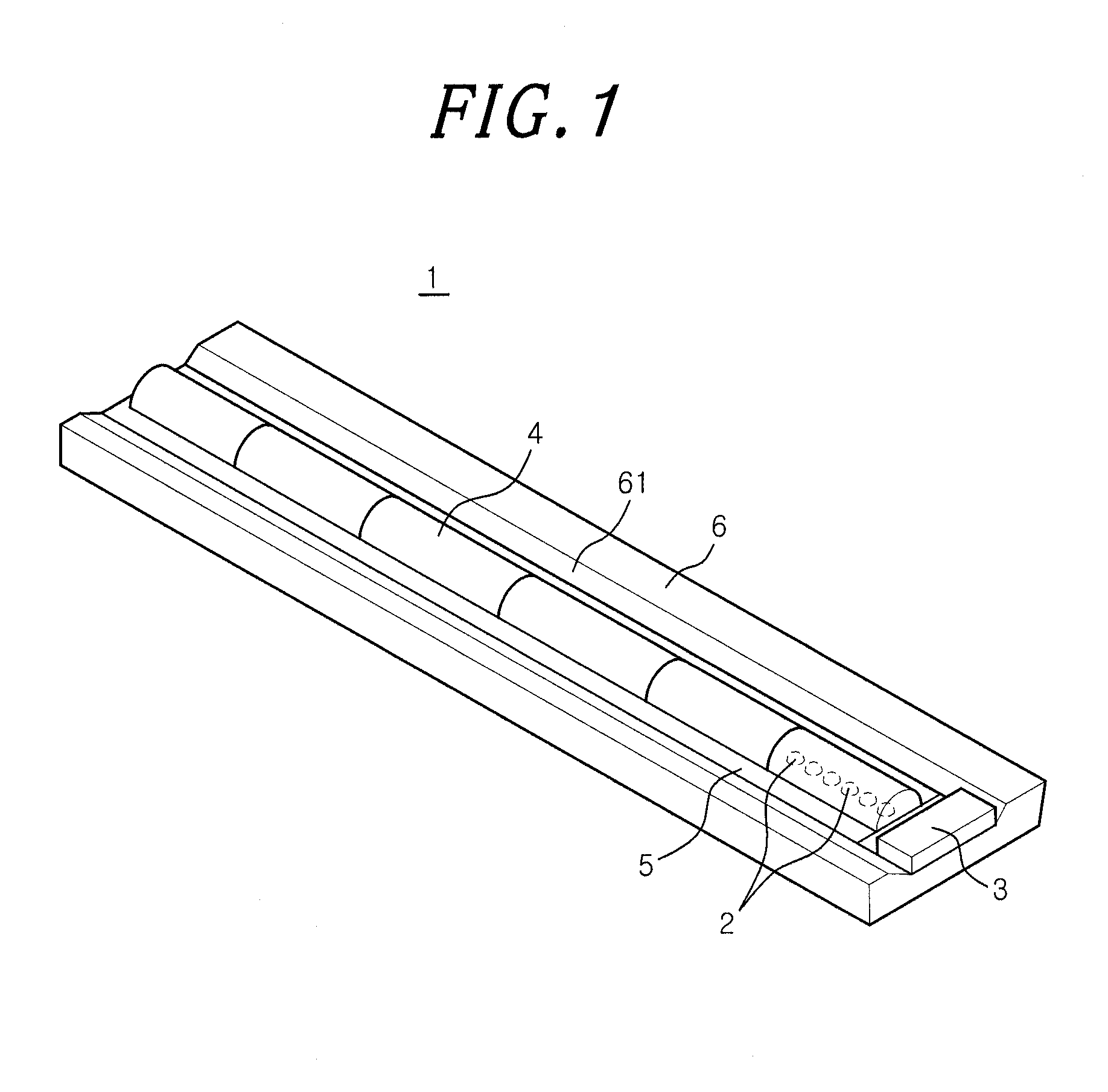
[0022]At first, a light emitting device in accordance with an embodiment of the present invention will be described with reference to FIGS. 1 to 4. As shown in FIG. 1, the light emitting device 1 of this embodiment includes a plurality of light emission units 2, and a driver 3 which drives the light emission units 2. A cover member 4 is commonly provided for the light emission units 2. Further, the light emitting device 1 includes a substrate 5 on which the light emission units 2 are mounted and a frame body 6 which holds the substrate 5.

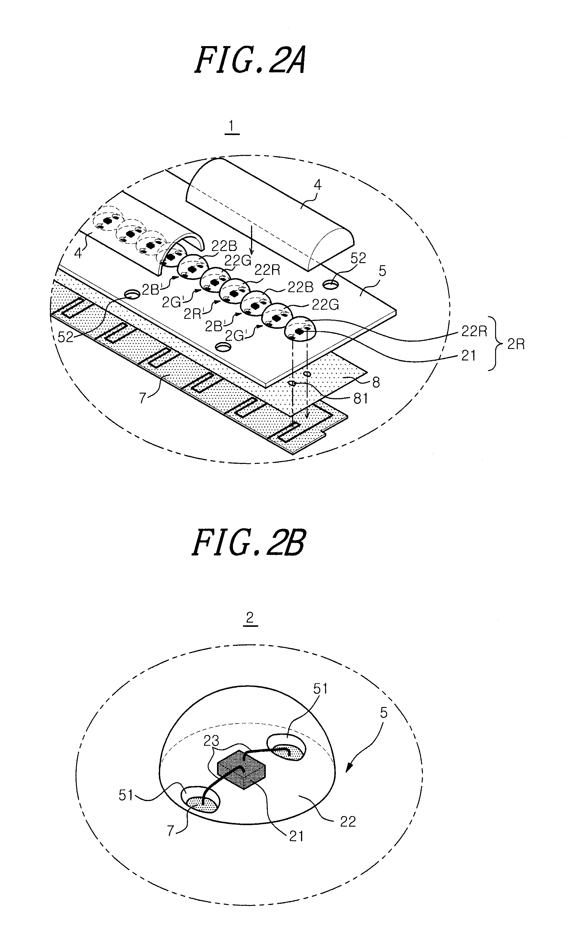
[0023]Referring to FIG. 2A, the substrate 5 is a rectangular board, and the light emission units 2 are m...


PUM

PropertyMeasurementUnit
thicknessaaaaaaaaaa
thicknessaaaaaaaaaa
color temperatureaaaaaaaaaa

Abstract

A light emitting device including multiple kinds of light emission units with different emission colors; a driver which drives the light emission units; and a cover member which is commonly provided for the multiple kinds of light emission units. The multiple kinds of light emission units include solid state light emitting elements of the same kind, and wavelength converters which cover the solid state light emitting elements, respectively, and convert wavelengths of lights emitted from the solid state light emitting elements into different wavelengths from each other. Further, the cover member contains a correction phosphor for correcting a chromaticity of light obtained by mixing lights emitted from the light emission units, to a predetermined chromaticity.

Description

FIELD OF THE INVENTION[0001]The present invention relates to a light emitting device including a plurality of solid state light emitting elements, and an illumination apparatus and a luminaire using same.BACKGROUND OF THE INVENTION[0002]A light emitting diode (LED) can achieve high luminance emission with low power. Accordingly, it has been used as a light source for various electrical apparatuses such as a display and an illumination apparatus. Recently, in addition to a red LED and a green LED, a blue LED has been put to practical use. Thus, it is possible to emit light having various colors by combining the three colors, i.e., red, green and / or blue of LEDs, or combining an LED with a phosphor which converts a wavelength of light emitted from the LED.[0003]Conventionally, there is known a light emitting device including a light emission unit using an LED as a light source and a light transmitting cover covering the surface of the light emission unit which are provided on a substr...

Claims


Application Information

Patent Timeline
Patent Type & Authority Applications(United States)
IPC IPC(8): F21V9/16F21V9/40
CPCF21V9/16F21V3/0463F21Y2101/02F21Y2113/007F21V3/0481H01L33/504H01L33/507H01L2224/48091H01L2224/45144F21K9/17H01L2924/00014H01L2924/00F21K9/27F21K9/64F21V3/08F21V3/12F21V9/38F21Y2113/17F21Y2115/10H01L24/45H01L2224/45124H01L2224/45139H01L2224/45147
Inventor TANAKA, KENICHIRO
Owner PANASONIC INTELLECTUAL PROPERTY MANAGEMENT CO LTD
Why Eureka
Try Eureka