Two-switch flyback power converters

a power converter and flyback technology, applied in the field of power converters, can solve the problems of affecting the use life of the power converter, the size and cost of the bulk capacitor in the switching power converter, and the dc-dc conversion has drawn much attention, so as to reduce the voltage ripple, the effect of cost saving and less capacitance of the bulk capacitor

Inactive Publication Date: 2013-09-12
FAIRCHILD TAIWAN
View PDF8 Cites 25 Cited by
  • Summary
  • Abstract
  • Description
  • Claims
  • Application Information

AI Technical Summary

Benefits of technology

[0008]The object of the present invention is to provide a two-switch Flyback power converter. The two-switch Flyback power converters with less capacitance of the bulk capacitor or bulk capacitor-less can reduce the voltage ripples at the output voltage for cost saving.
[0009]A two-switch Flyback power converter according to the present invention comprises a transformer, a first switch, a second switch, and a control circuit. The transformer includes a primary-winding and a secondary-winding. The primary-winding is coupled to a power source of the two-switch Flyback power converter and has a first winding and a second winding. The first switch is coupled to switch the first winding. The second switch is coupled to switch the first winding and the second winding. The control circuit generates a first-drive signal and a second-drive signal to control the first switch and the second switch for switching the transformer and regulating an output of the two-switch Flyback power converter. The first switch and the second switch can deliver more power in a valley of the rectified power source by switching different winding to improve ripples of an output voltage of the two-switch Flyback power converter.

Problems solved by technology

In recent years, the size and cost problem of the bulk capacitor in switching power converters has drawn much attention.
In addition, the quality of the bulk capacitor influences the usage life of the power converters.

Method used


Image

  • Two-switch flyback power converters
  • Two-switch flyback power converters
  • Two-switch flyback power converters

Examples


Embodiment Construction

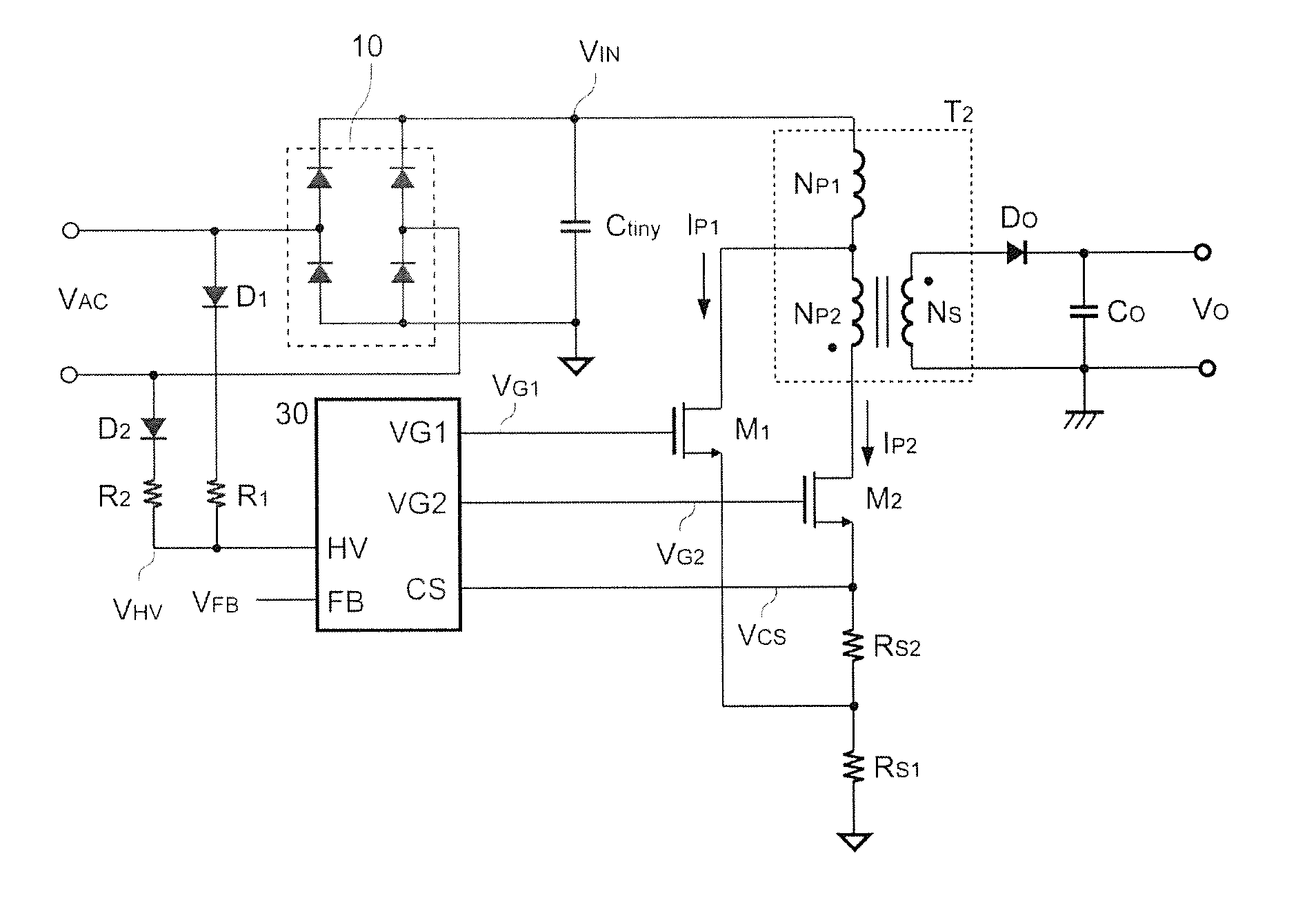
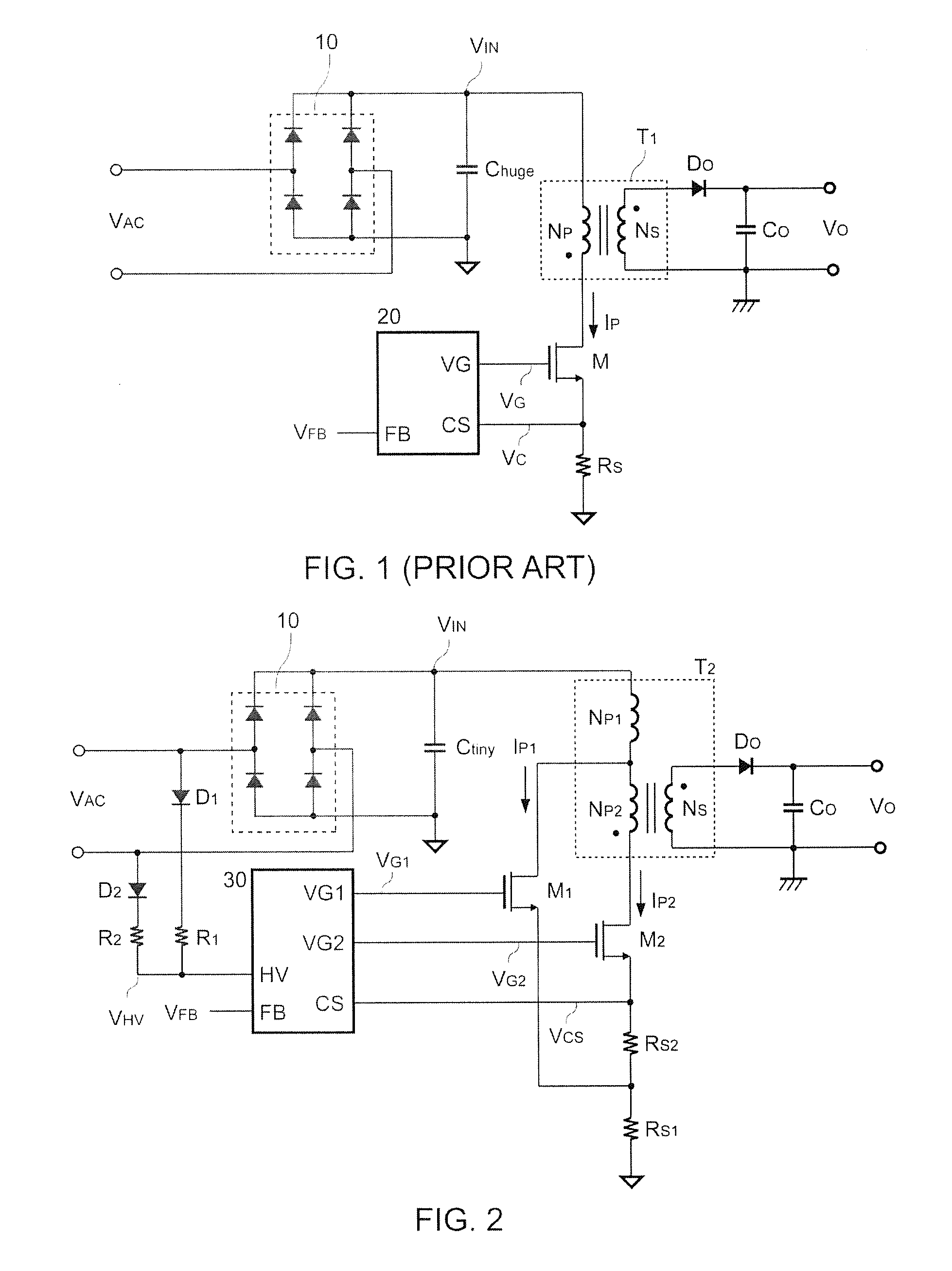
[0017]FIG. 2 is a circuit diagram of an embodiment of two-switch Flyback power converters according to the present invention. A rectifier can be a full-wave rectifier having a first diode D1 and a second diode D2 according to one embodiment of the present invention, anodes of the first diode D1 and the second diode D2 are connected to the power source VAC. respectively. Cathodes of the first diode D1 and the second diode D2 are together connected to a high-voltage terminal HV of a control circuit 30 through a first-series resistor R1 and a second-series resistor R2. A high-voltage signal VHV is generated at the high-voltage terminal HV through the full-wave rectification of the first diode D1 and the second diode D2. Thus, the rectifier is coupled to the power source VAC for rectifying the power source VAC to generate the high-voltage signal VHV. The bridge rectifier 10 including a plurality of diodes rectifies the power source VAC to generate the input voltage VIN. A bulk capacitor...


PUM


Abstract

A two-switch Flyback power converter is disclosed. The two-switch Flyback power converter comprises a transformer, a first switch, a second switch, and a control circuit. The transformer includes a primary-winding and a secondary-winding. The primary-winding has a first winding and a second winding. The first switch is coupled to switch the first winding. The second switch is coupled to switch the first winding and the second winding. The control circuit generates a first-drive signal and a second-drive signal to control the first switch and the second switch for switching the transformer and regulating an output of the two-switch Flyback power converter. The two-switch Flyback power converter with less capacitance of the bulk capacitor or bulk capacitor-less can reduce the voltage ripples at the output voltage for cost saving.

Description

REFERENCE TO RELATED APPLICATION[0001]This application is based on Provisional Application Ser. No. 61 / 609,572, filed 12 Mar. 2012, currently pending.BACKGROUND OF THE INVENTION[0002]1. Field of Invention[0003]The present invention relates to a power converter, and more particularly, the present invention relates to a two-switch Flyback power converter.[0004]2. Description of Related Art[0005]FIG. 1 shows a traditional Flyback topology of power converters. A transformer T1 includes a primary-winding NP and a secondary-winding NS. A first terminal of the primary-winding NP is coupled to receive a DC input voltage VIN. The secondary-winding NS generates an output voltage VO via a rectifier DO and a capacitor CO. A drain terminal of a power switch M is coupled to a second terminal of the primary-winding NP. A sense resistor RS is coupled between a source terminal of the power switch M and a ground. A switching current IP flows through the primary-winding NP and the power switch M when ...

Claims


Application Information

Patent Timeline
Patent Type & Authority Applications(United States)
IPC IPC(8): H02M3/156
CPCH02M3/156H02M1/14H02M2001/0022H02M7/217H02M3/33569H02M1/0022
Inventor HUANG, WEI-HSUAN
Owner FAIRCHILD TAIWAN
Why Eureka
Try Eureka