
Solenoid actuators using embedded printed circuit coils

Inactive Publication Date: 2013-09-12
GUMMIN MARK A +2
View PDF5 Cites 29 Cited by
  • Summary
  • Abstract
  • Description
  • Claims
  • Application Information

AI Technical Summary

Benefits of technology

The present invention is a method and apparatus that applies PCB techniques to create solenoid actuators and similar electromagnetic motor devices. The invention eliminates the traditional wire wound coil and replaces it with printed coil structures embedded in multilayer circuit boards. This results in a more compact device with stronger coil connections. The invention guides the flux lines with a shaft and a metal or ferromagnetic frame or housing, which increases the efficiency of the device. Most components can be assembled using standard PCB fabrication processes, making the device more affordable and robust. The mass of wirewound coils is eliminated, and fragile electrical connections of existing solenoids are replaced with fixed, robust connections, improving the reliability of the device.

Problems solved by technology

But wound wire coils are not without their drawbacks and limitations.
From an operational standpoint, motors and solenoids are prone to failure due to thermal cycling or mechanical stress on the fragile connections within the coil.
Tiny copper wires, thermal cycling, heavy iron assemblies, and hand-assembly processes eventually lead to failure of the device at the weakest points.
Thus none of the benefits of modern PCB techniques and their economies of scale have been directed to ameliorate the drawbacks of traditional solenoid actuator designs.

Method used


Image

  • Solenoid actuators using embedded printed circuit coils
  • Solenoid actuators using embedded printed circuit coils
  • Solenoid actuators using embedded printed circuit coils

Examples


Embodiment Construction

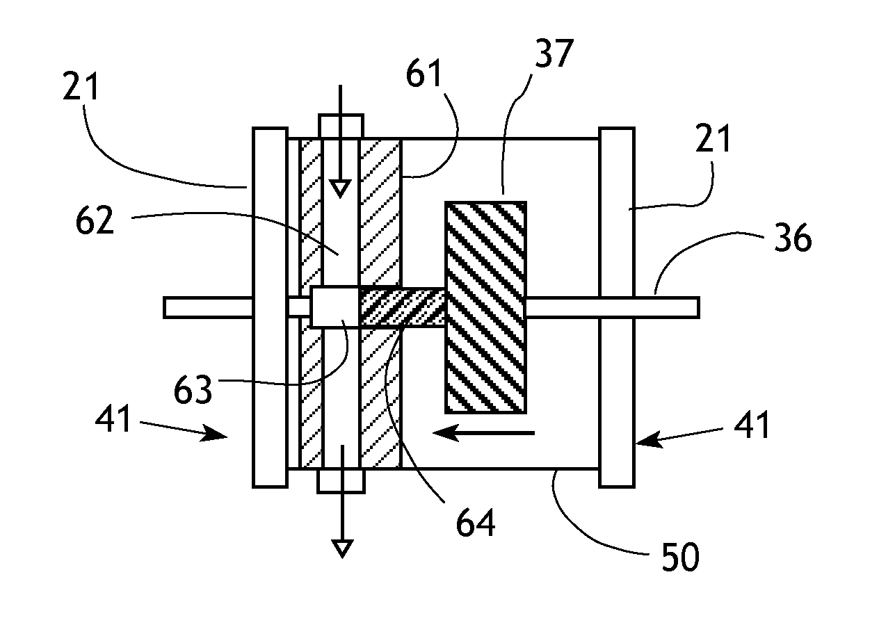
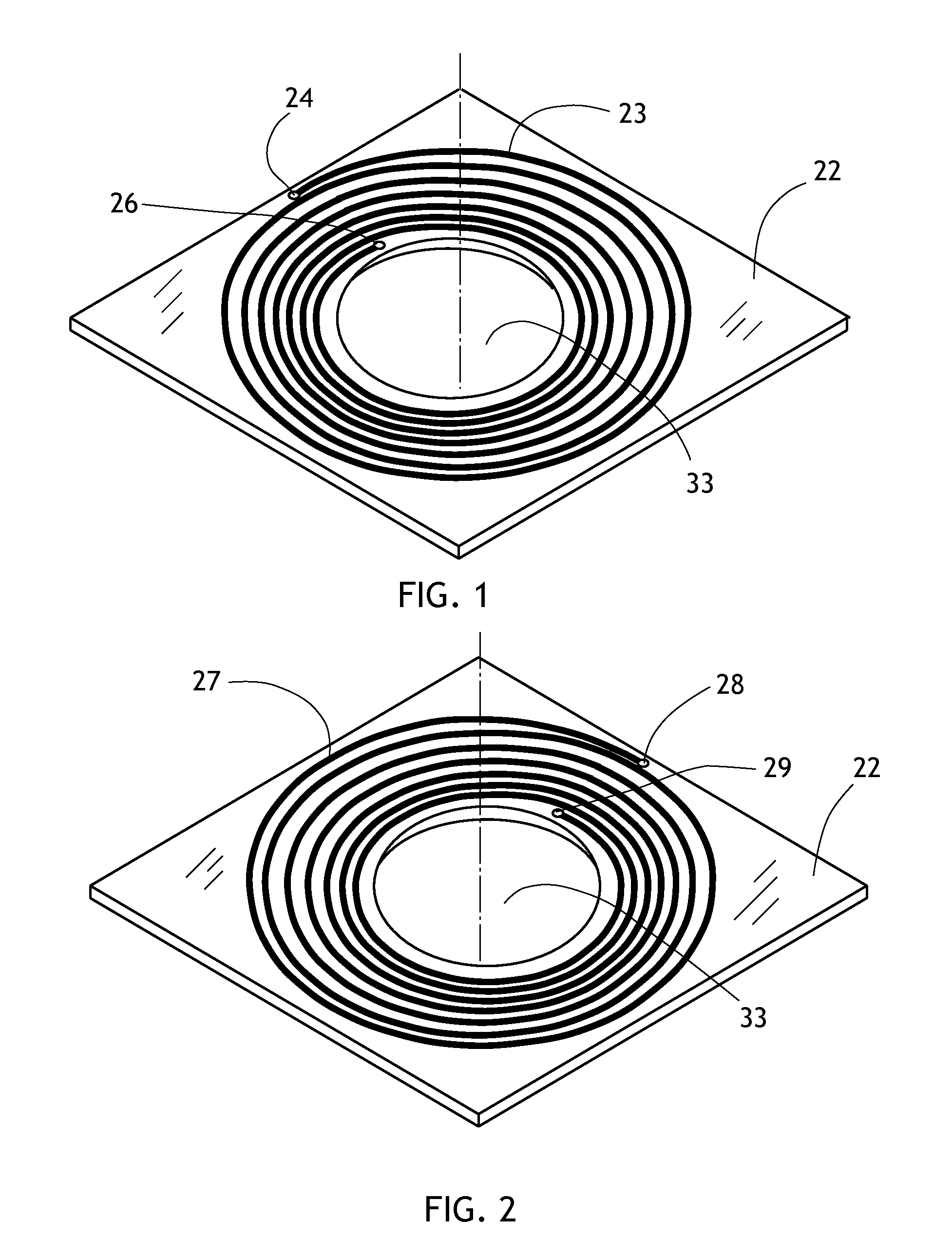
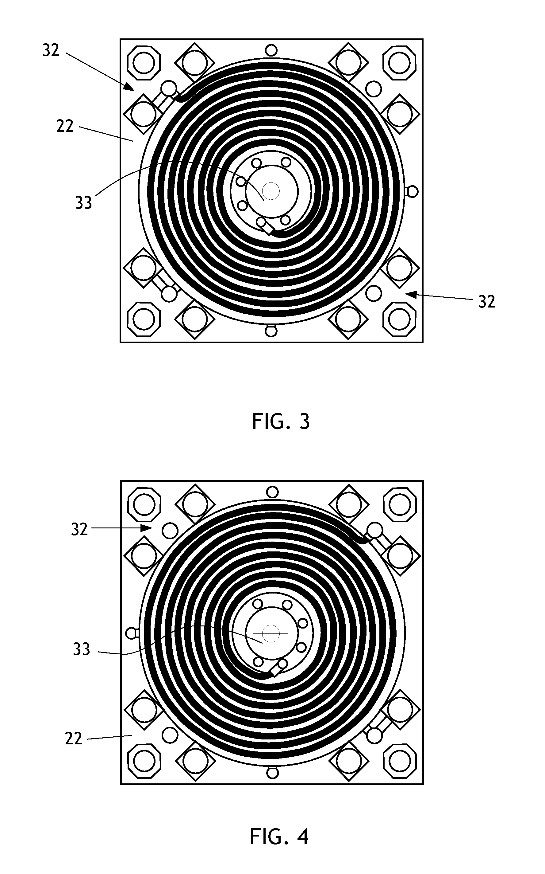
[0034]The present invention generally comprises a method and apparatus for construction of solenoid actuators and similar electromagnetic motor devices that employ printed coil structures that are embedded in multilayer circuit boards. With regard to FIGS. 1-6, a significant feature of the invention is the use of one or more embedded printed circuit electromagnetic coils 21 as a driver element for electromagnetic linear and rotary motors. Each embedded coil 21 is comprised of a plurality of individual lamina 22, each having a spiral conductor 23 printed on one surface and a spiral conductor 27 printed on the reverse side. A central opening 33 extends coaxially through the coil 21, and may be lined with a bushing (not shown). Conductor 23 terminates at its outer extent at contact pad / via 24 and at its inner extent at contact pad / via 26, while conductor 27 terminates at its outer extent at contact pad / via 28 and at its inner extent at contact pad / via 29. Each conductor may include as ...


PUM


Abstract

A magnetomotive device has an embedded electromagnetic coil formed of multiple printed conductor segments on multiple lamina of a multilayer PCB. A shaft extends through an opening in the PCB, and a permanent magnet with axially opposed poles is secured to the shaft. Energizing the embedded electromagnet generates a magnetic field that attracts or repels the permanent magnet, driving the shaft to do useful work. A pair of embedded PCB coils may be employed, the shaft extending through both coils with the permanent magnet disposed therebetween, and the coils energized so that one repels the permanent magnet while the other attracts it, and the shaft may be driven reversibly to do useful work.

Description

CROSS-REFERENCE TO RELATED APPLICATIONS[0001]This application claims filing date priority based on Provisional Applications No. 61 / 685,003, filed Mar. 9, 2012, and No. 61 / 686,305, filed Apr. 3, 2012.FEDERALLY SPONSORED RESEARCH[0002]Not applicable.SEQUENCE LISTING, ETC ON CD[0003]Not applicable.BACKGROUND OF THE INVENTION[0004]1. Field of the Invention[0005]This invention relates to linear electromagnetic motors and, more particularly, to solenoid actuators used for driving switches, valves, pumps, and similar loads.[0006]2. Description of Related Art[0007]Traditional motors and solenoids use loops of insulated copper magnet-wire wound (or ‘turned’) around a bobbin or similar hollow structure to create a magnetic field that provides motive force to a moving core of ferromagnetic material when the coil is energized. Bobbins of magnet wire have been in wide use since the publication of Michael Faraday's research in 1831 and are used for motors, solenoids, and countless other applicati...

Claims


Application Information

Patent Timeline
IPC IPC(8): H02K41/02F04B43/00H02K33/02
CPCF04B43/043H02K41/02H02K33/02H01F2007/068F16K31/082H01F7/1646F04B43/00
Inventor GUMMIN, MARK A.COHEN, HOWARDDONAKOWSKI, WILLIAM
Owner GUMMIN MARK A
Learn More