Glenoid extension block

a technology of glenoid and extension block, which is applied in the field of implants, can solve the problems of requiring a significant amount of time and specific skills of surgeons, and the instability of shoulder joints, and achieve the effect of simplifying the repair

Active Publication Date: 2013-09-12
ARTHREX
View PDF52 Cites 51 Cited by
  • Summary
  • Abstract
  • Description
  • Claims
  • Application Information

AI Technical Summary

Benefits of technology

[0006]The embodiments are based on the object of simplifying the repair of a fractured/degenerat...

Problems solved by technology

Such fractures, also known as Bankart lesion lead to continuing shoulder instability.
Here harvesting...

Method used


Image

  • Glenoid extension block
  • Glenoid extension block
  • Glenoid extension block

Examples


Embodiment Construction

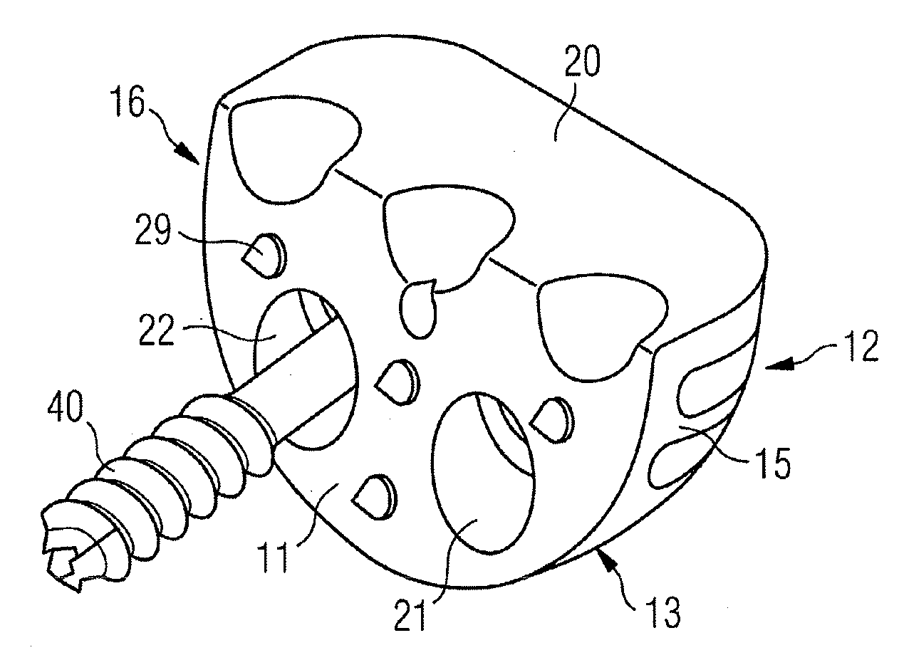
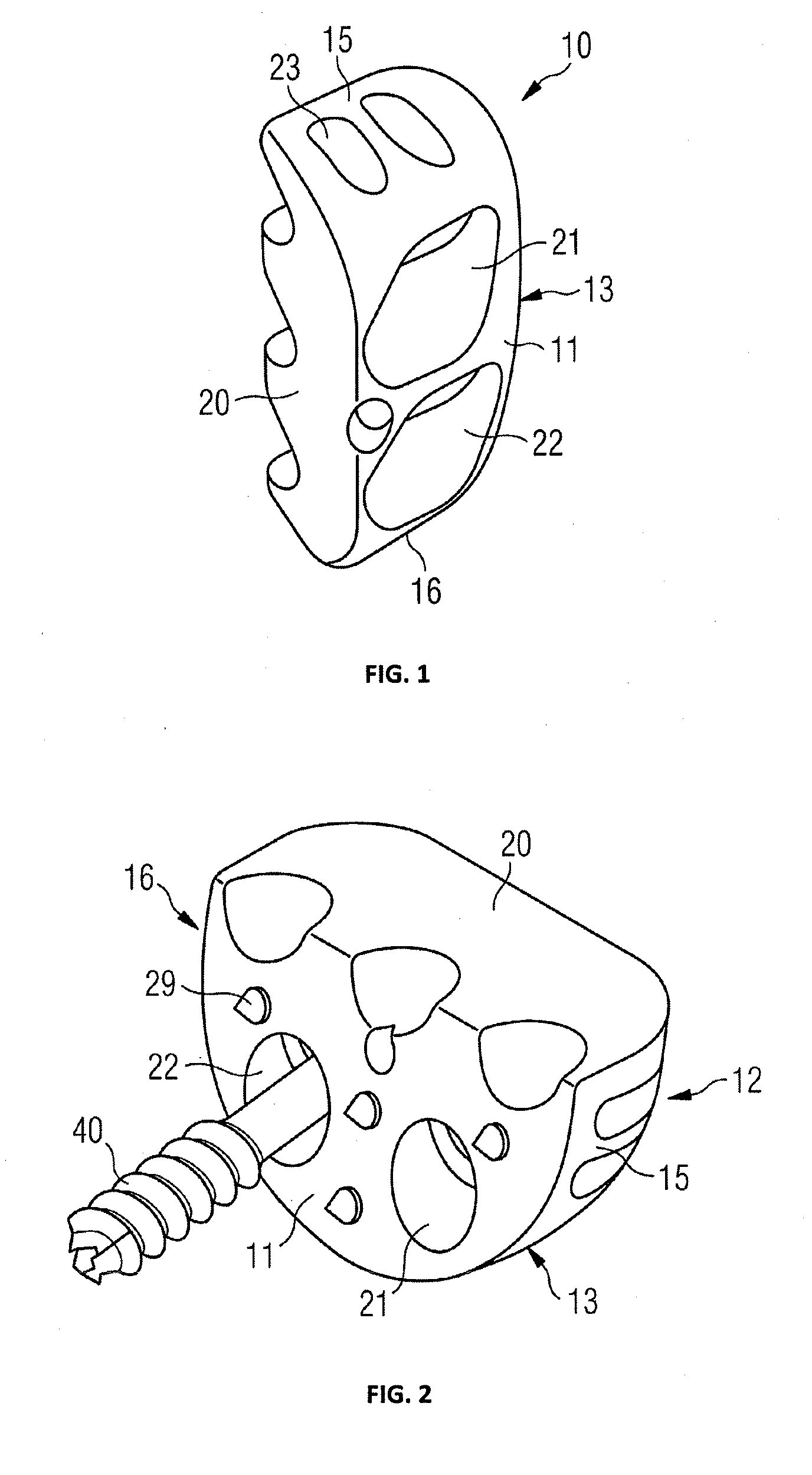
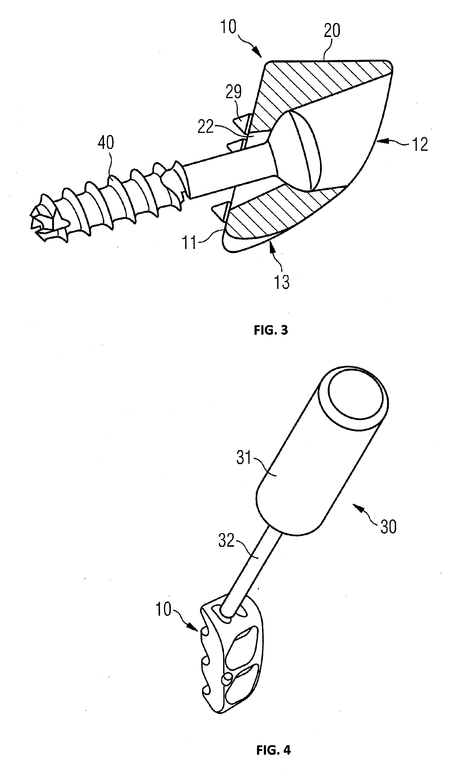
[0026]In FIG. 1, a preferred embodiment is shown. The glenoid implant 10 has a mounting surface 11 by which it is attached to the glenoid. Mounting surface 11 may have a 3-dimensional structure contacting the glenoid to enhance bone ingrowth. The glenoid implant preferably has cuboidal shape. Although it may have any other shape as long as it allows fixation to the glenoid and adaption to the glenoid surface. There may be a rear surface 12 opposed to the mounting surface. The top surface 14 may have a recess serving as contact surface 20 adapted to the surface form of the glenoid 50 and to interface with the humerus head. Opposed to the top surface is a bottom surface 13. There are a first sidewall 15 and a second sidewall 16 which are preferably rounded. In the sidewall 15 there is a hole 23, which may be used to align the implant with at lest one guide pin, which has previously been placed in the bone. Furthermore, such a hole may be used by a handle for holding the implant. Two h...


PUM


Abstract

A glenoid implant has an anatomically formed body including of metal and/or plastic materials. It further has a contact surface adapted to extend the surface of a glenoid and to bear a humerus. In the implant body, there is at least one hole with a screw head seating area for holding the head of a screw, which may be screwed into a glenoid for fixedly attaching the glenoid implant.

Description

CROSS-REFERENCE TO RELATED APPLICATIONS[0001]This application claims priority to pending European Application No. 12157196.2, filed on 27 Feb. 2012.BACKGROUND OF THE INVENTION[0002]1. Field of the Invention[0003]The invention relates to an implant for increasing stability of the shoulder and specifically in the treatment of anterior shoulder instability.[0004]2. Description of Relevant Art[0005]Fractures of the anterior glenoid may be caused by anterior shoulder dislocation. Such fractures, also known as Bankart lesion lead to continuing shoulder instability. WO 2008 / 015670 A2 and EP 2 135 566 A1 disclose instruments and methods for repairing such a fracture by fixing a coracoid graft to the glenoid. Here harvesting, shaping, drilling and shuttling require a significant amount of time and specific skills of the surgeon. Cup shaped and ball shaped joint prosthesis are disclosed in EP 1 815 825 A1, EP 1 510 190 A1, FR 2825 263 A1, FR 2 843 293 A1 and FR 2 578 162 A1.SUMMARY OF THE INV...

Claims


Application Information

Patent Timeline
IPC IPC(8): A61F2/40
CPCA61F2/30767A61F2002/30261A61F2/4612A61F2/4081A61F2002/30731
Inventor HARDY, PHILIPPENAUDIN, STEPHANE
Owner ARTHREX
Why Eureka
Try Eureka