Vehicle control apparatus and vehicle control method
- Summary
- Abstract
- Description
- Claims
- Application Information
AI Technical Summary
Benefits of technology
Problems solved by technology
Method used
Image

Examples
first embodiment
[0048]A vehicle control apparatus according to a first embodiment of the present invention will now be described.
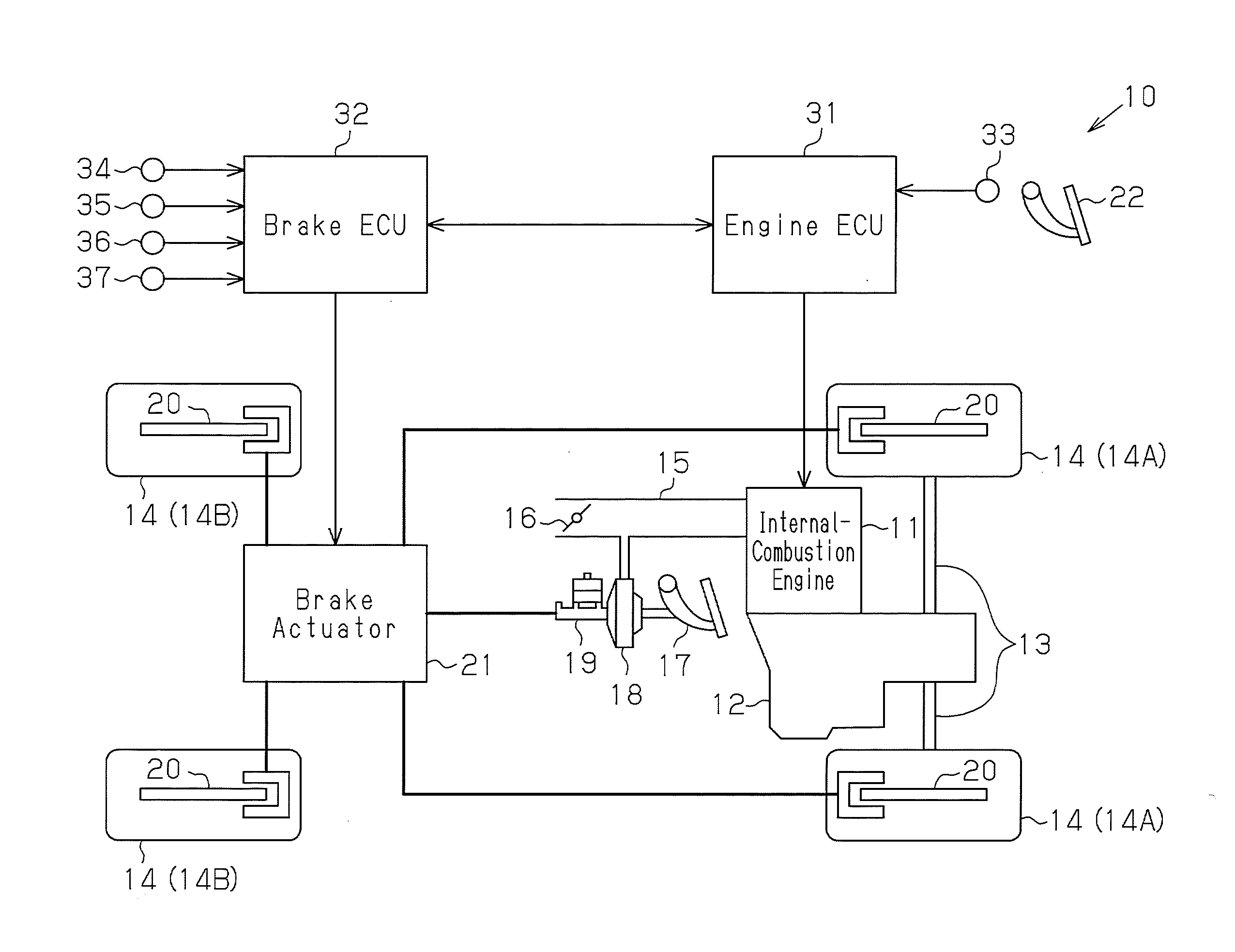
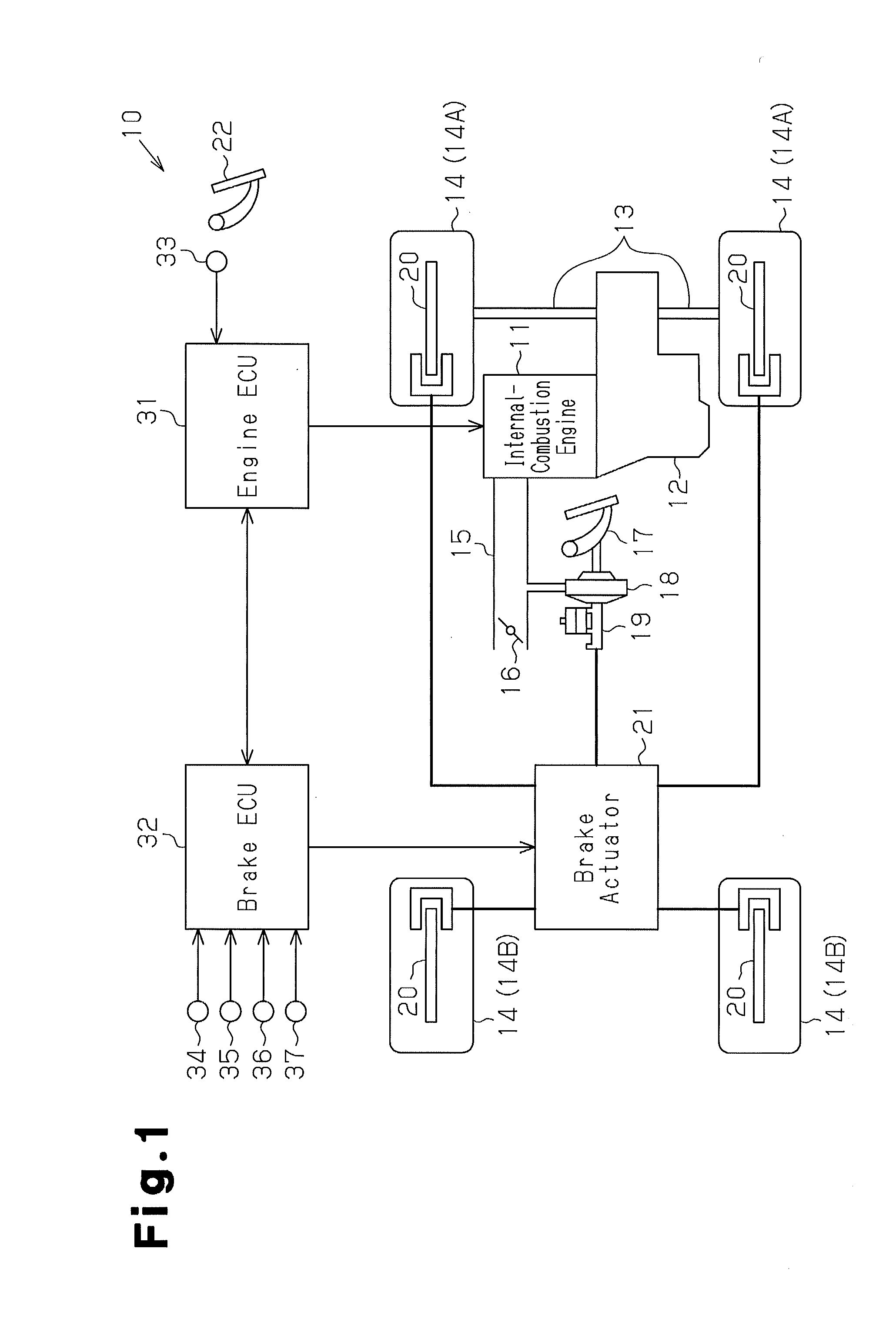
[0049]As shown in FIG. 1, an internal-combustion engine 11 as a driving source is mounted on a vehicle 10. An output torque of the internal-combustion engine 11 is transmitted to wheels 14 via a multistage automatic transmission 12 with a plurality of gears and an axle 13. The vehicle 10 is a front-wheel-drive vehicle, in which front ones of the wheels 14 function as drive wheels 14A, to which the output torque of the internal-combustion engine 11 is transmitted, and rear ones of the wheels 14 function as coasting wheels 14B, to which the output torque is not transmitted.
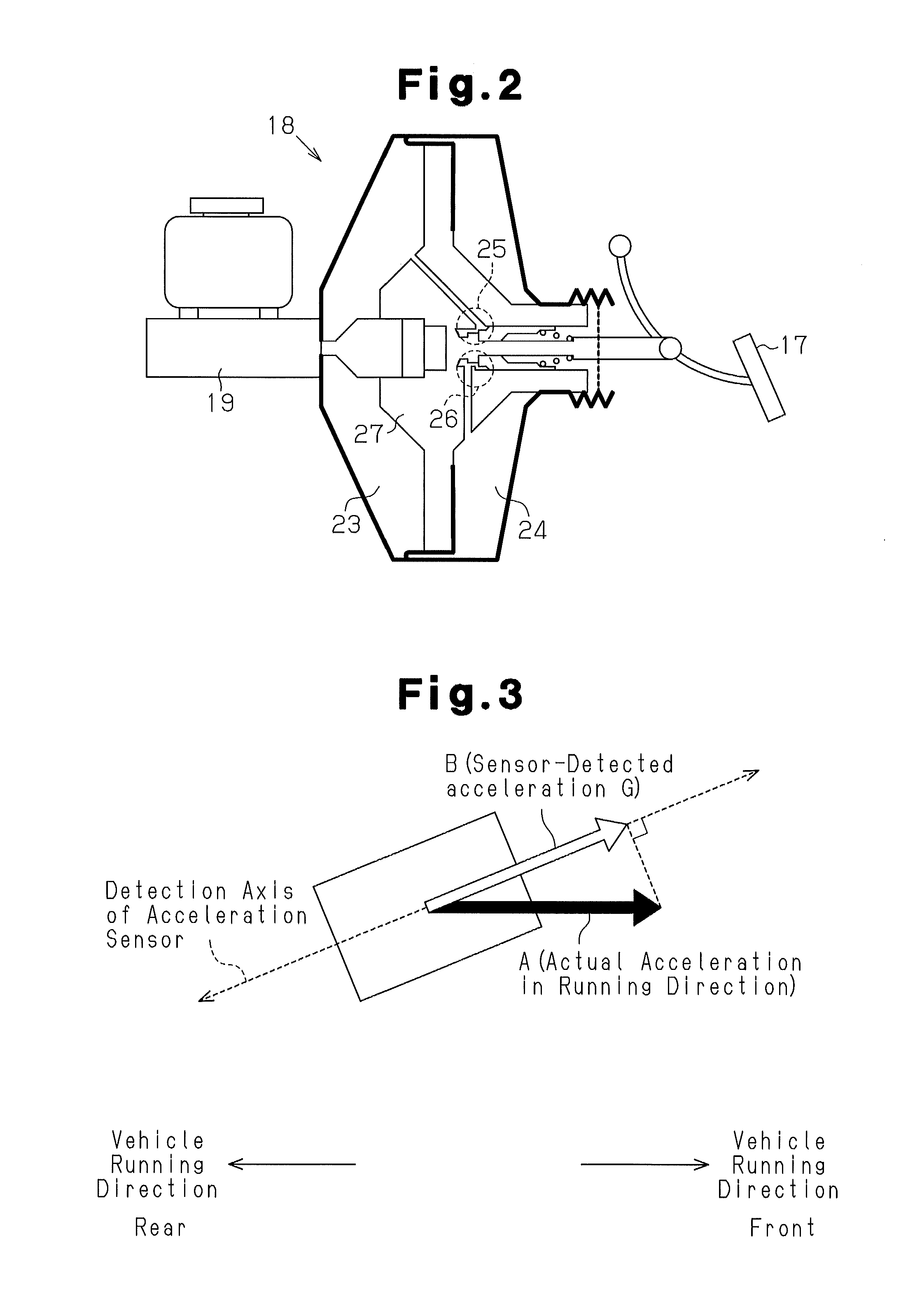
[0050]The vehicle 10 has a brake booster 18, which doubles and transmits depressing operation force (depressing force) of a brake pedal 17 using an intake air negative pressure generated downstream a throttle valve 16 in an intake air passage 15 of the internal-combustion engine 11. Further, the vehicle 1...
second embodiment
[0131]A vehicle control apparatus according to a second embodiment of the present invention will now be described. The differences from the first embodiment will mainly be described. In the present embodiment, the same reference numerals are given to parts that are common with the first embodiment and a detailed description thereof is omitted.
[0132]In the first embodiment, when the vehicle 10 is in a slip state, the restriction of the output of the internal-combustion engine 11 by the BOS is inhibited. In contrast, in the present embodiment, even if the vehicle 10 is in a slip state, the restriction of the output of the internal-combustion engine 11 by the BOS is not inhibited (namely, the restriction of the output is permitted) when a difference ΔV between the rotation speed of the drive wheels 14A and the rotation speed of the coasting wheels 14B of the vehicle 10 is greater than or equal to a determination value J2. According to an apparatus of the present embodiment, the acceler...
third embodiment
[0147]A vehicle control apparatus according to a third embodiment of the present invention will now be described. The differences from the first embodiment will mainly be described. In the present embodiment, the same reference numerals are given to parts that are common with the first embodiment and a detailed description thereof is omitted.
[0148]In the first embodiment, the negative pressure correction coefficient Cvc is computed on the basis of the booster negative pressure Pv detected by the pressure sensor 37, and the negative pressure correction coefficient Cvc is used as an estimation parameter for the master pressure estimated value PesPm. In contrast, in the present embodiment, the pressure sensor 37 is not provided. Accordingly, the negative pressure correction coefficient Cvc is not computed, and the master pressure estimated value PesPm is estimated without using the negative pressure correction coefficient Cvc. Further, in the present embodiment, the brake ECU 32 as a c...
PUM
 Abstract
Description
Claims
Application Information
 - R&D
- Intellectual Property
- Life Sciences
- Materials
- Tech Scout
- Unparalleled Data Quality
- Higher Quality Content
- 60% Fewer Hallucinations
Browse by: Latest US Patents, China's latest patents, Technical Efficacy Thesaurus, Application Domain, Technology Topic, Popular Technical Reports.
© 2025 PatSnap. All rights reserved.Legal|Privacy policy|Modern Slavery Act Transparency Statement|Sitemap|About US| Contact US: help@patsnap.com