Acoustical wave measuring apparatus

a technology for measuring apparatus and acoustic waves, applied in the direction of instruments, applications, ultrasonic/sonic/infrasonic diagnostics, etc., can solve problems such as forming gaps to disable the acquisition of acoustic signals, and achieve the effect of ease of handling

Inactive Publication Date: 2013-09-19
CANON KK
View PDF2 Cites 8 Cited by
  • Summary
  • Abstract
  • Description
  • Claims
  • Application Information

AI Technical Summary

Benefits of technology

[0009]According to the present invention, a solid matching agent is not necessary, and an image acquisition is not limited to a particular range. Additionally, attachment of a matching agent is also unnecessary, which leads to ease of handling. Furthermore, since a sealing member is biased to be movable, even when the distance between a holding member and a probe changes during scanning, an acoustic match between the probe and the holding member can be maintained.
[0010]Further features of the present invention will become apparent from the following description of exemplary embodiments with reference to the attached drawings.

Problems solved by technology

This may form a gap to disable acquisition of acoustic signals.

Method used


Image

  • Acoustical wave measuring apparatus
  • Acoustical wave measuring apparatus
  • Acoustical wave measuring apparatus

Examples


first embodiment

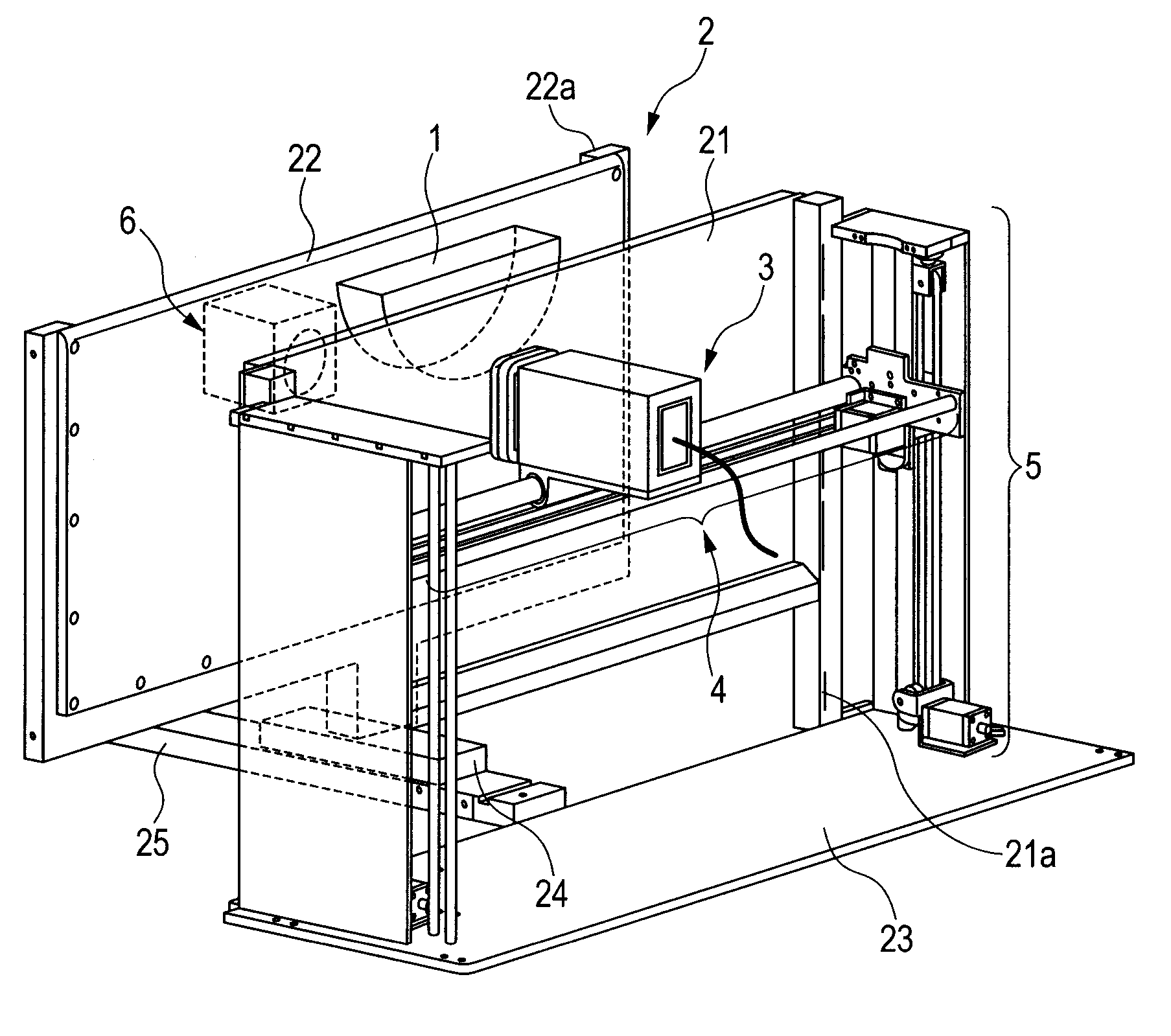
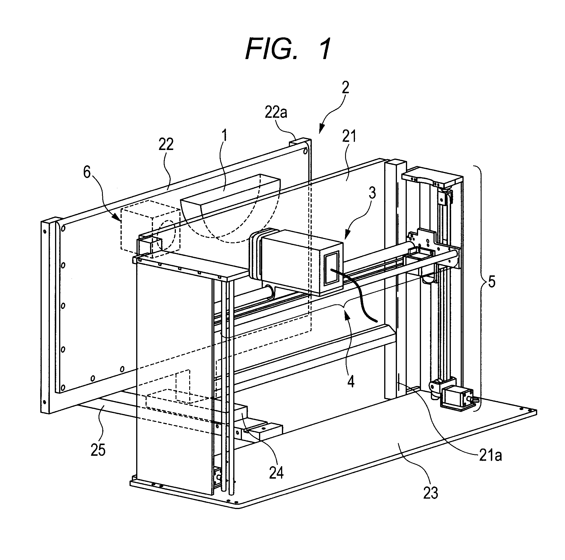
[0026]FIG. 1 illustrates a main portion of an ultrasonic apparatus as a first embodiment of an acoustical wave measuring apparatus according to the present invention. The ultrasonic apparatus according to the present embodiment is an ultrasonic apparatus of a mechanical scanning type which acquires an image of the inside of a living body using photoacoustic effects. The ultrasonic apparatus according to the present embodiment includes a holding mechanism 2 for holding the position of a living body 1 serving as a test object, a probe unit 3, a horizontal scanning mechanism 4, a vertical scanning mechanism 5, and a light projecting unit 6. The probe unit 3 is a unit for receiving acoustical waves. The horizontal scanning mechanism 4 and vertical scanning mechanism 5 are mechanisms for running the probe unit 3 for scanning horizontally and vertically with respect to a fixed holding plate 21. The light projecting unit 6 is a unit for applying light to the living body 1. The living body ...

second embodiment

[0036]A second embodiment is a modification of the first embodiment and is different in the configuration of a probe unit. Components other than a probe unit in the second embodiment are the same as the components in the first embodiment, and a description of the components will be omitted. As illustrated in FIG. 6A that is a schematic view of a probe unit 8 in the present embodiment, the probe unit 8 includes a probe 81, a housing 82, an oil seal 83, a linear motion base 84, a rotation base 85, and a compression spring 86. The probe 81 is fixed to the housing 82. The rotation base 85 is attached to the linear motion base 84 so as to rotate about X. Since the oil seal 83 is attached to the rotation base 85, the oil seal 83 is also rotatable. The oil seal 83 is made of an elastic body which enables the oil seal 83 to follow inclination of a fixed holding plate 21 and absorb deformation of the fixed holding plate 21 within a range 83a where the probe 81 contacts the fixed holding plat...

third embodiment

[0040]FIG. 7A is a schematic view of a probe unit 9 and a carrier 41 according to a third embodiment. In the present embodiment, the probe unit 9 is provided to be rotatable about Y with respect to the carrier 41. The probe unit 9 includes a probe 91, a housing 92, an oil seal 93, an oil seal base 94, and a compression spring 95. The probe 91 is coupled to the housing 92. The oil seal 93 is coupled to the oil seal base 94. The oil seal base 94 and housing 92 have a fitting portion 92a. With this configuration, the oil seal base 94 is movable in a normal direction of a receiving surface of the probe 91 with respect to the housing 92 while the oil seal base 94 is biased toward a fixed holding plate 21 by a biasing force of the compression spring 95. The movable distance of the oil seal 93 is set to be larger than an amount of deformation of the fixed holding plate 21 caused by a force generated when a living body 1 is held.

[0041]FIG. 7B is a sectional view of a state of the probe unit...


PUM


Abstract

An acoustical wave measuring apparatus capable of achieving an acoustic match even when the shape of a holding member changes largely along a scanning direction of a probe, including a holding member which holds a test object, a probe which receives an acoustical wave, and a sealing member, and the acoustical wave is received by running the probe for scanning with respect to the holding member while an acoustic matching agent for performing acoustic impedance matching between the probe and the holding member is injected into between a receiving surface and the holding member. The sealing member includes a portion with elasticity arranged at the receiving surface of the probe and is biased in a direction which brings the sealing member into contact with the holding member such that the portion contacts the holding member to seal a space between the receiving surface and the holding member.

Description

TECHNICAL FIELD[0001]The present invention relates to an apparatus for measuring an acoustical wave, such as an ultrasonic apparatus adapted to run a probe for scanning along a scanning guide.BACKGROUND ART[0002]Ultrasonic apparatuses which acquire image information of a test object by running an ultrasonic probe for mechanical scanning have been known. Since an apparatus using ultrasonic waves performs acoustic impedance matching, the apparatus needs to be configured such that there is no gap to admit air between members, between which ultrasonic waves are transmitted. Note that an acoustic impedance match, an acoustic match, acoustic impedance matching in this specification means that the difference between the values of the acoustic impedances of two different substances is not more than about 20%. In the case of mechanical scanning, if the shape of a surface of a test object changes along a direction in which a probe is run for scanning, the distance between the probe and the te...

Claims


Application Information

Patent Timeline
Patent Type & Authority Applications(United States)
IPC IPC(8): G01H15/00
CPCA61B8/0825G01H15/00A61B8/4281A61B8/4209
Inventor NAKABAYASHI, TAKAAKI
Owner CANON KK
Why Eureka
Try Eureka