Smooth surface forming tool and manufacture thereof

a surface forming and smooth technology, applied in the field of composite forming tools, can solve the problems of outer surfaces and limit the aerodynamic efficiency of airframe structures, and achieve the effect of cost-effectiveness

Active Publication Date: 2013-09-19
SAAB AB
View PDF7 Cites 5 Cited by
  • Summary
  • Abstract
  • Description
  • Claims
  • Application Information

AI Technical Summary

Benefits of technology

[0059]In such way the production of the aircraft article forming tool's composite face sheet can be performed in one working step which is cost-effective.

Problems solved by technology

The materials- and manufacturing technology used today, producing such outer surfaces, limits the aerodynamic efficiency of the airframe structures, e.g. regarding the possibility to achieve laminar air flow over a wing, fin, blade, control surface etc.

Method used


Image

  • Smooth surface forming tool and manufacture thereof
  • Smooth surface forming tool and manufacture thereof
  • Smooth surface forming tool and manufacture thereof

Examples


Embodiment Construction

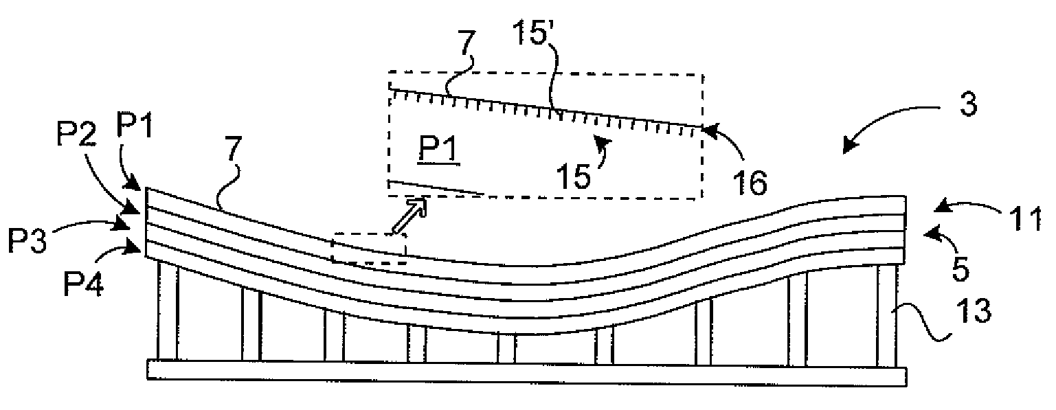
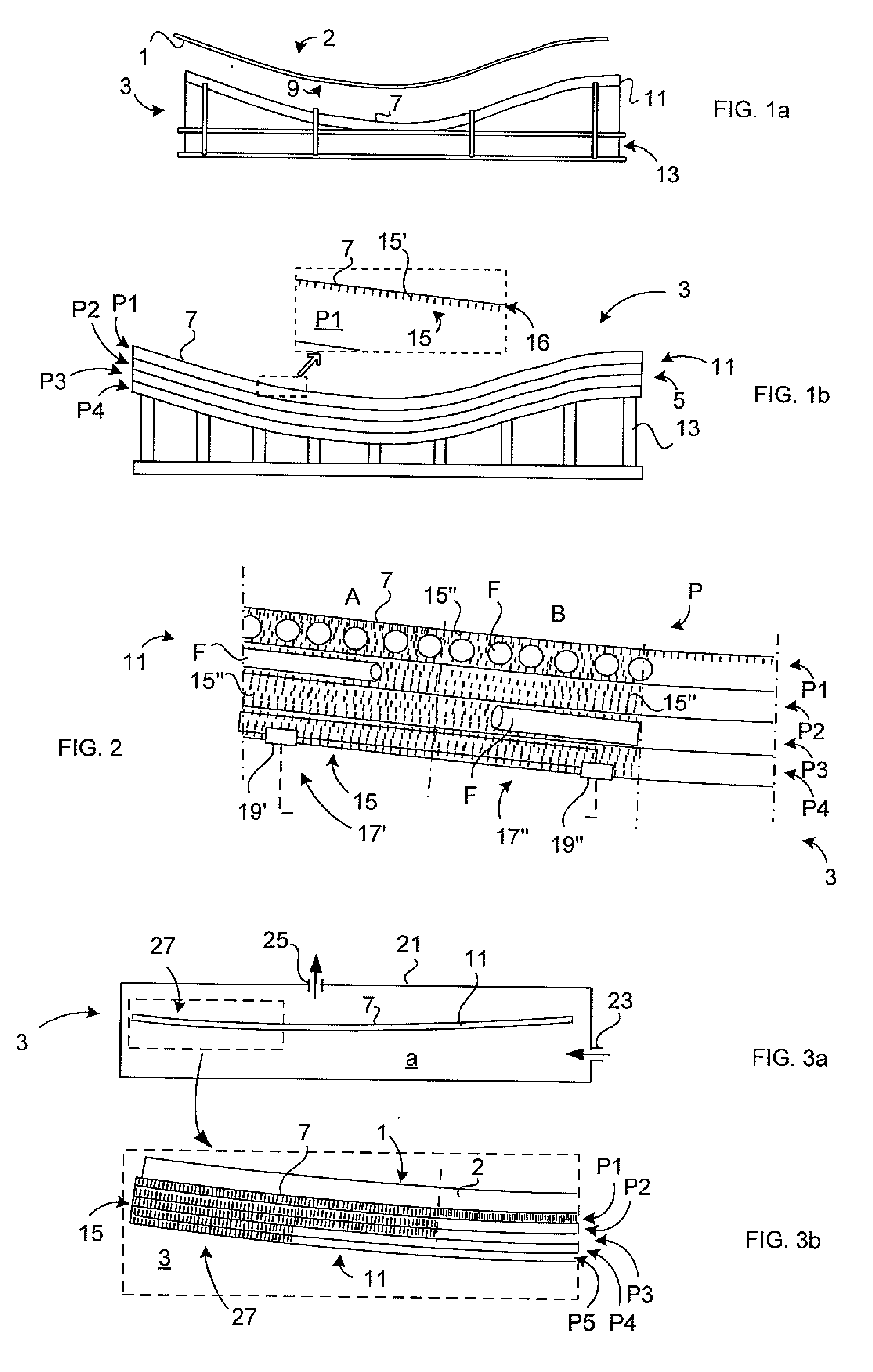
[0071]Hereinafter, embodiments of the present invention will be described in detail with reference to the accompanying drawings, wherein for the sake of clarity and understanding of the invention some details of no importance are deleted from the drawings. Also, the illustrative drawings show nano structures of different types, being illustrated extremely exaggerated and schematically for the understanding of the invention. The conductive nano structures are illustrated exaggerated in the figures also for the sake of understanding of the orientation and the alignment of the conductive nano filaments.

[0072]FIG. 1a schematically illustrates a blank 1 to be formed on a composite forming tool 3. The blank 1 shown in FIG. 1a comprises carbon fibres with different fibre orientations. The blank 1 is formed and cured on a forming surface 7 of the composite forming tool 3. The finished article formed of the blank is an aircraft article 2. The aircraft article is thus made of fibre reinforced...


PUM

PropertyMeasurementUnit
lengthaaaaaaaaaa
thicknessaaaaaaaaaa
diameteraaaaaaaaaa

Abstract

An aircraft article composite forming tool and a method for producing the tool. The aircraft article to be formed includes a composite material including an outer surface. The aircraft article composite forming tool includes a matrix laminate made of at least an upper ply including a forming surface for forming the aircraft article and outer surface. The upper ply includes a nano filament structure embedded therein.

Description

TECHNICAL FIELD[0001]The present invention relates to a composite forming tool according to the preamble of claim 1 and a method of manufacture of the tool according to claim 12.[0002]The invention primary regards manufacturers of aircraft article forming tools for manufacture of aircraft articles having an outer surface designed as an aerodynamic surface.BACKGROUND ART[0003]Articles, such as composite (or polymeric material) airframe structures of the type wing skins, fin skins, control surfaces, wind turbine blades, open rotor blades etc., having aerodynamic function, are designed and manufactured with a certain surface texture / roughness for enhancing the laminar airflow over the airframe's skin surface (i.e. the outer surface or aerodynamic surface of the article). The outer surface serves as an aerodynamic surface when the article is subjected for an air stream.[0004]It is thus important that the aerodynamic surface is formed in such way that it becomes smooth. A smooth aerodyna...

Claims


Application Information

Patent Timeline
Patent Type & Authority Applications(United States)
IPC IPC(8): B64F5/00
CPCB29C33/40B29C70/443Y10T156/10B29K2105/165B64F5/0009B29C70/88B64F5/10B29C45/73H05B2214/04B82Y30/00
Inventor HALLANDER, PERPETERSSON, MIKAELWEIDMANN, BJORNGRANKALL, TOMMYSTRINDBERG, GOTENORDIN, PONTUS
Owner SAAB AB
Why Eureka
Try Eureka