Cement retainer and squeeze technique

Inactive Publication Date: 2013-09-19
NINE DOWNHOLE TECHNOLOLGIES LLC
View PDF7 Cites 19 Cited by
  • Summary
  • Abstract
  • Description
  • Claims
  • Application Information

AI Technical Summary

Benefits of technology

[0006]A novel cement retainer and novel squeeze technique are disclosed below. Although the cement retainer and wiper plug may be specially designed for the purpose, it is convenient and desirable that the cement retainer and wiper plug be time tested reliable equipment thereby avoiding the problems of newly designed equipment. To this end, the cement retainer may comprise a more-or-less conventional ball drop plug assembly or comparable device having a passage there

Problems solved by technology

Given a cost of $50,000/day for a land rig or $250,000

Method used


Image

  • Cement retainer and squeeze technique
  • Cement retainer and squeeze technique
  • Cement retainer and squeeze technique

Examples


Example

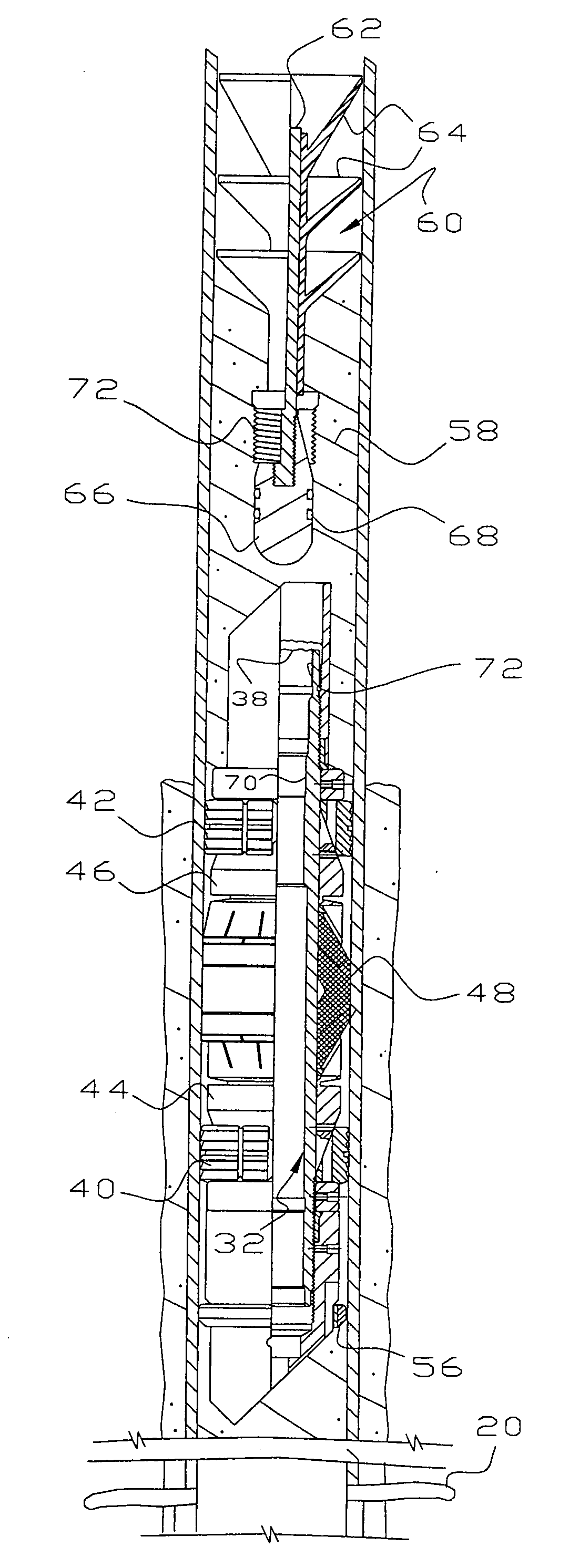
[0017]The present invention relates to cement retainers for use in hydrocarbon wells drilled into the earth to squeeze a material known in the field as cement through perforations in a well casing. The materials from which the tools are made are subject to considerable variation. Some of the components can be of drillable metal and some can be of composite material. A composite material can be a fabric core impregnated with a resin which is hardened in some suitable manner. Any components left in the well are usually made of drillable materials. Various changes and adaptations can be made in the tools without departing from the spirit and scope of the invention, which is to be measured solely by the claims themselves.

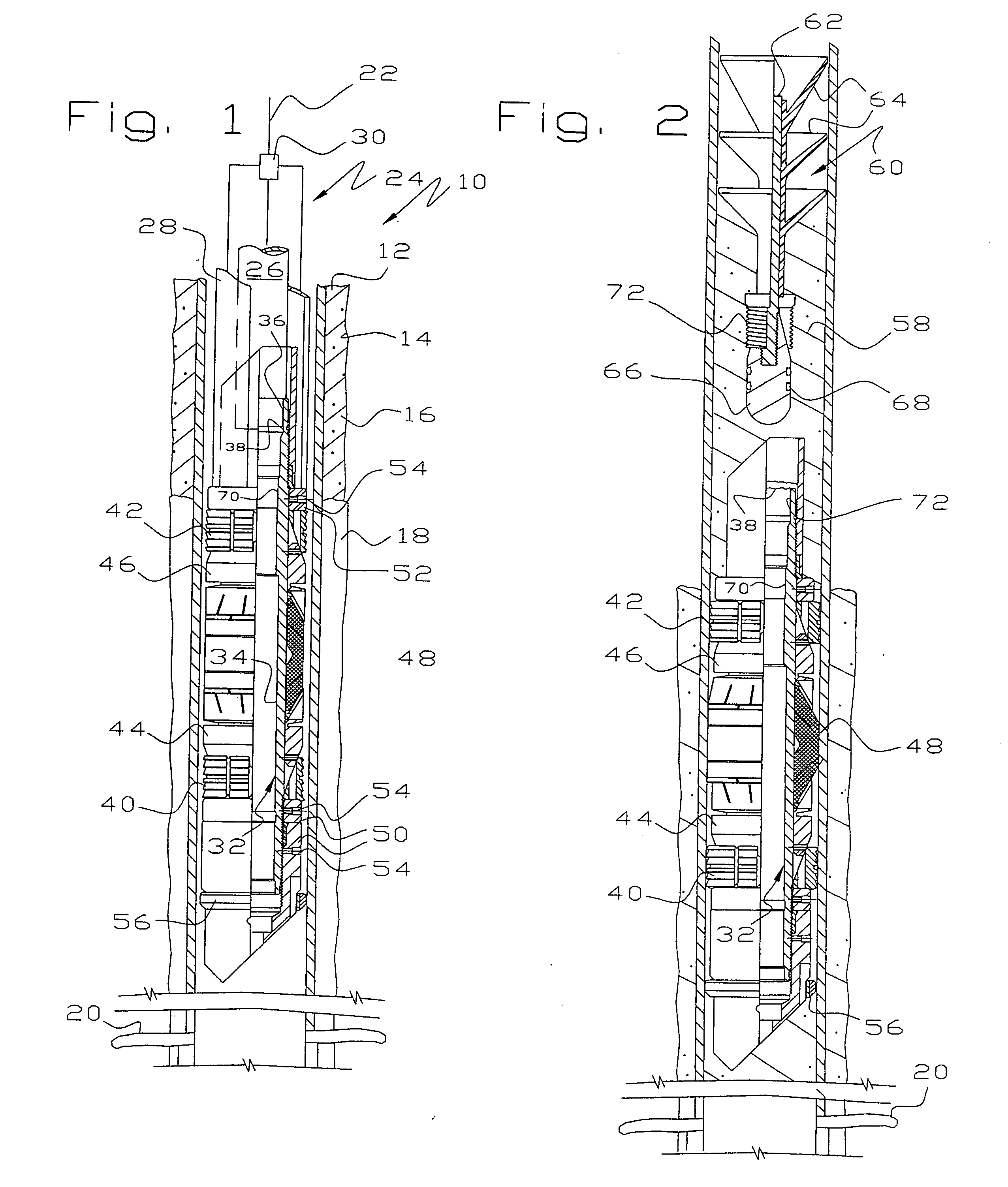
[0018]Referring to FIGS. 1-2, there is illustrated a cement retainer 10 being run into a hydrocarbon well inside casing 12 which has been cemented in a well bore 14 by a cement sheath 16. The cement sheath 16 is illustrated as being discontinuous by the presence of gas ...


PUM


Abstract

A cement retainer comprises a plug that may be run into casing on a wire line and set in a conventional manner. A passage through the plug allows cement to be pumped therethrough. A wiper plug follows the cement, wipes the inside of the casing and latches onto the retainer to prevent back flow of cement. In some embodiments, the cement retainer and wiper plug are made of drillable materials allowing a series of squeeze operations to be conducted, one after another without undue delay, and then be drilled up in a single bit run. In some embodiments, the cement retainer and wiper plug are made of metals, drillable or non-drillable, or other long lived materials in order to plug wells in the process of abandoning them.

Description

[0001]This invention relates to a cement retainer and technique to squeeze perforations in a hydrocarbon well.BACKGROUND OF THE INVENTION[0002]Cement is used in almost all hydrocarbon wells to isolate a section of a pipe string or well bore. The most common cementing operation is to cement a pipe string or casing in a well bore to secure the pipe string and seal off the contents of formations penetrated by the well bore. This is often called primary cementing and involves pumping cement into the casing and then pumping a wiper plug down the casing so it pushes the cement out of the bottom of the casing through a float shoe or collar into which the wiper plug latches. The cement travels upwardly through the annulus between the casing and the well bore and ultimately sets up to secure the casing in the well bore and seal off the formations penetrated by the well bore.[0003]Another common cementing operation occurs when it is necessary or desirable to place cement between casing and th...

Claims


Application Information

Patent Timeline
IPC IPC(8): E21B33/00E21B34/00E21B33/12
CPCE21B33/134E21B33/13
Inventor FRAZIER, W. LYNN
Owner NINE DOWNHOLE TECHNOLOLGIES LLC
Why Eureka
Try Eureka