Vibration generator

a generator and vibration technology, applied in the field of vibration generators, can solve the problems of generating noise, reducing the amplitude coefficient, and reducing the quality of the motor, so as to prevent undue prevent noise generation, and rapid stop the vibration of the vibrating body

Active Publication Date: 2013-09-19
SANYO SEIMITSU
View PDF8 Cites 21 Cited by
  • Summary
  • Abstract
  • Description
  • Claims
  • Application Information

AI Technical Summary

Benefits of technology

[0026]The damper member of the vibration generator of the present invention does not impede the vibration of the vibrating body while the vibrating body makes vibration. The damper member of the vibration generator of the present invention can rapidly stop the vibration of the vibrating body when an electric current flowing throug...

Problems solved by technology

In case of the technology disclosed in JP2002-263557A, it is however difficult to manufacture a motor having a stably low Q value (amplitude increasing coefficient).
Accordingly, the technology disclosed in JP2002-263557A involves difficulties in improving vibration frequency characteristics and suppressing undue vibration of the vibrating body.
This is a cause of generating noises.
In the solution means in which the fluid such as grease or magnetic fluid is filled into the vibration generator, if the viscosity of the fluid is low, it is i...

Method used


Image

  • Vibration generator
  • Vibration generator
  • Vibration generator

Examples


first preferred embodiment

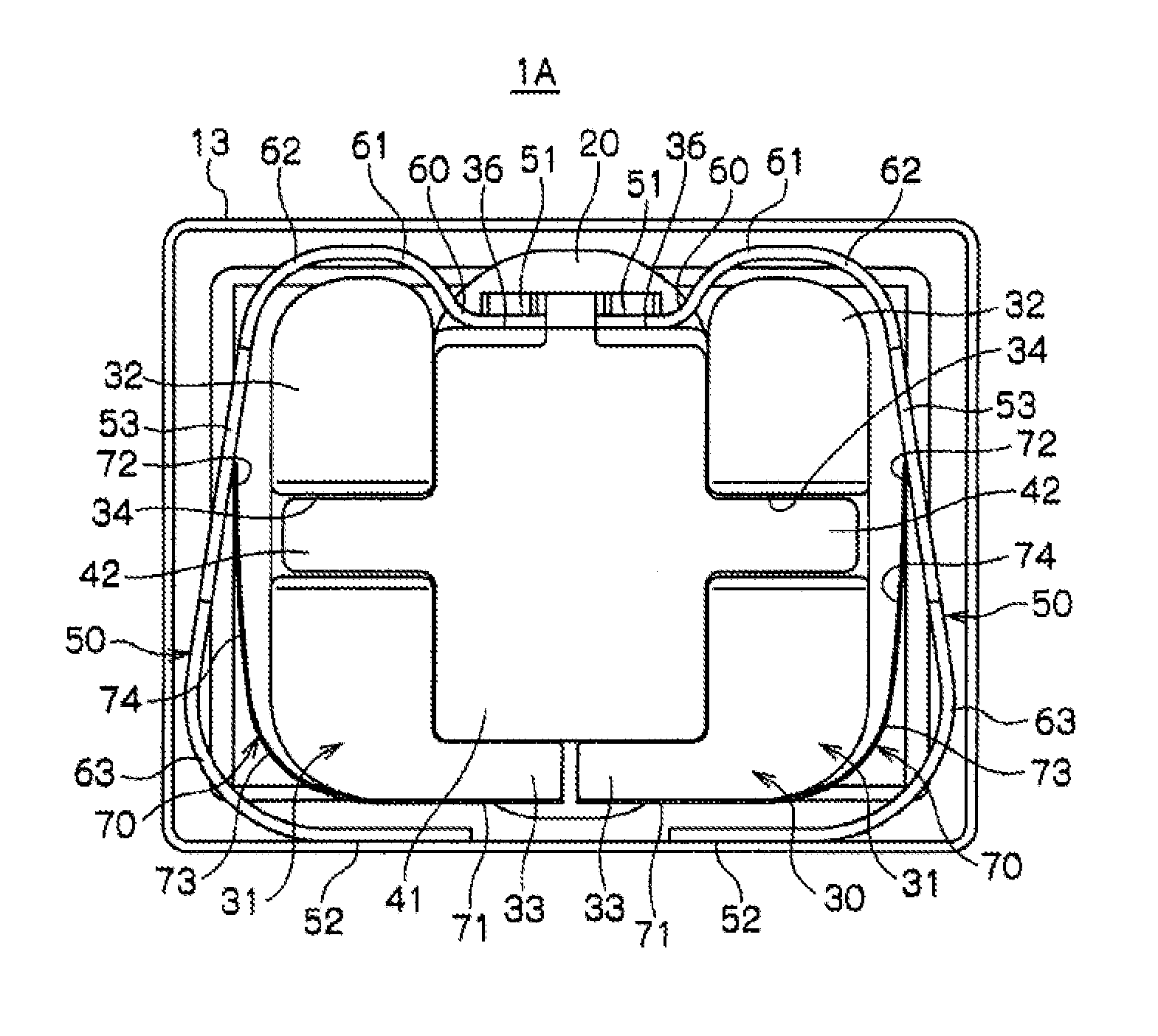
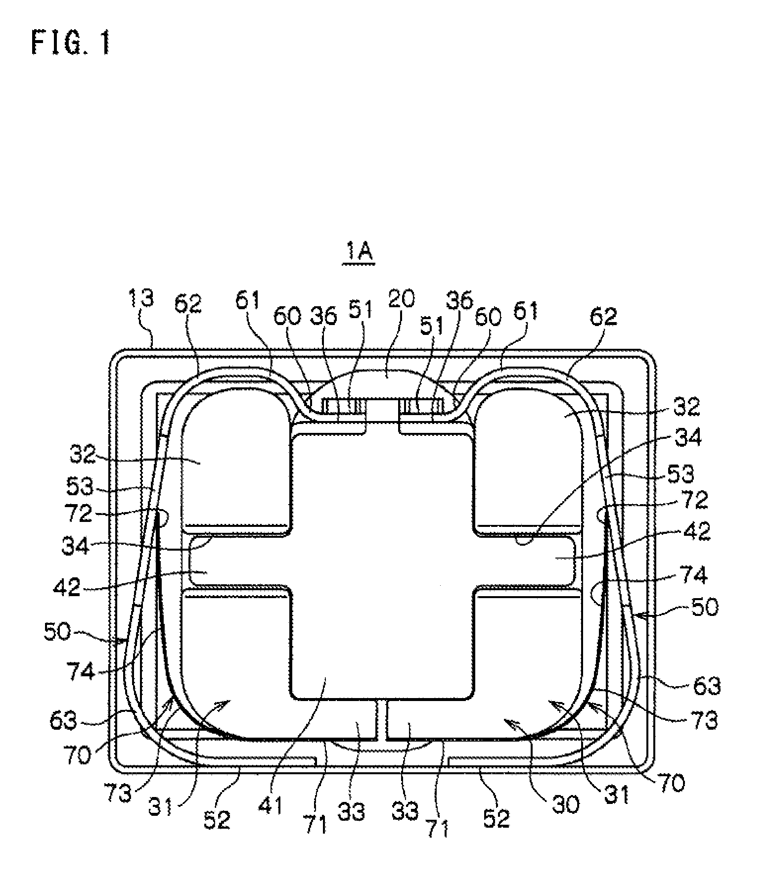
[0042]The basic configuration of the vibration generator 1A according to the first preferred embodiment of the present invention is as follows.

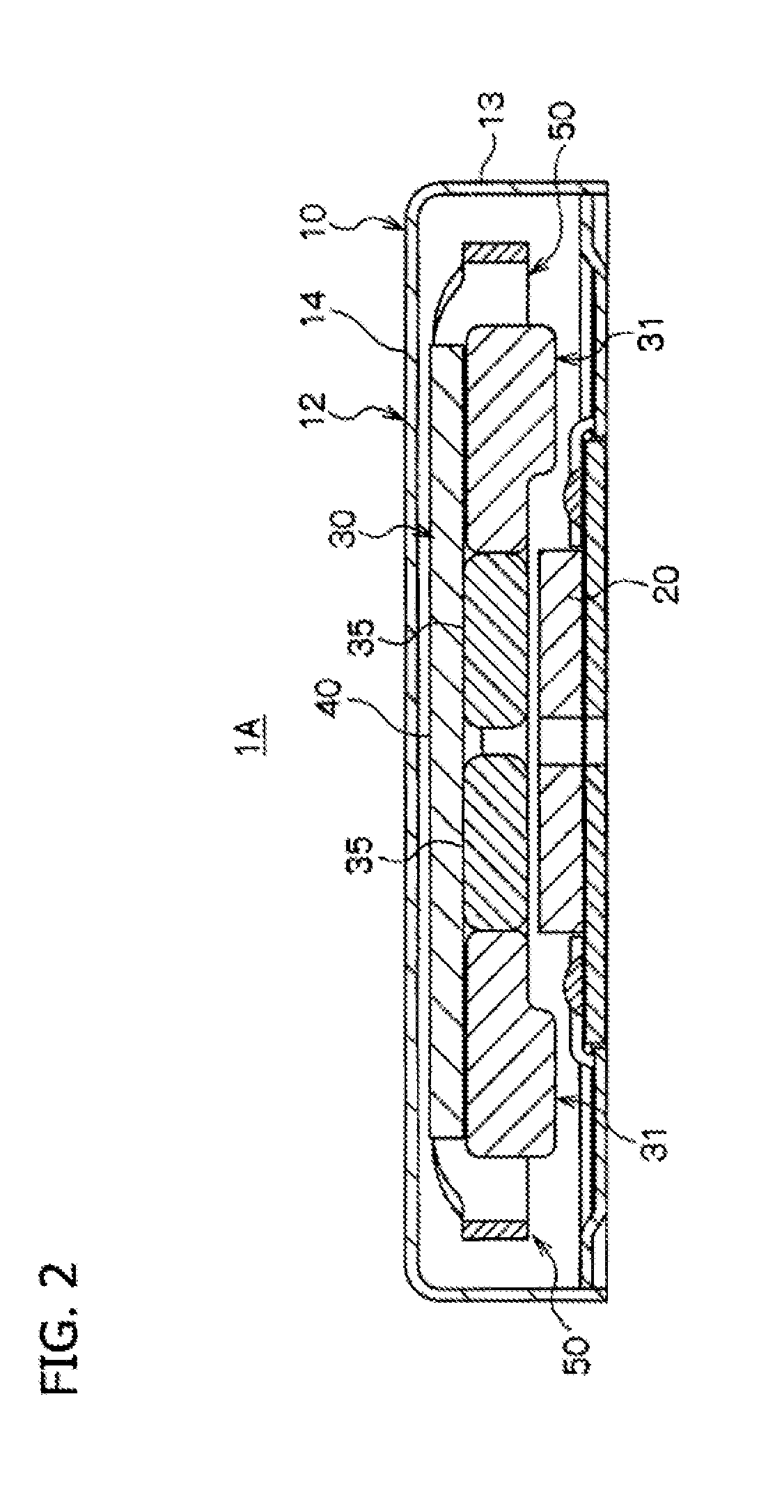
[0043]Referring to FIGS. 1 through 3, the vibration generator 1A preferably includes a housing 10 making up an outer shell. The housing 10 preferably includes a bottom member 11 and a case 12 capped on the bottom member 11. The case 12 preferably includes a circumferential wall portion 13 extending along the peripheral edge of the case 12 and a top portion 14 closing the top end of the case 12.

[0044]A coil 20 is arranged within the housing 10 and is positioned on the bottom member 11. A vibrating body 30 is arranged within the housing 10 in an opposing relationship with the coil 20. Band-shaped leaf springs 50 for supporting the vibrating body 30 with respect to the circumferential wall portion 13 are arranged within the housing 10.

[0045]The coil 20 is a hollow-core spiral coil formed by spirally winding a wire so that a space can be defined ...

second preferred embodiment

[0088]In the second preferred embodiment, the vibration generator 1B preferably includes damper members 80 differing in configuration from the damper members 70 of the first preferred embodiment. The vibration generator 1B of the second preferred embodiment remains the same as the vibration generator 1A of the first preferred embodiment in terms of the configurations other than the damper members 80. Therefore, the configurations of the vibration generator 1B of the second preferred embodiment remaining the same as those of the vibration generator 1A of the first preferred embodiment will be designated by like reference symbols and will be described only briefly. Detailed description will be made on only the differing configurations.

[0089]As shown in FIGS. 8 and 9, the vibration generator 1B of the second preferred embodiment preferably includes a housing 10 making up an outer shell of the vibration generator 1B. The housing 10 is made of a non-magnetic material and is small in heig...


PUM


Abstract

A vibration generator includes a circumferential wall portion, a vibrating body arranged inside the circumferential wall portion in an opposing relationship with a coil and configured to reciprocatingly vibrate in one direction, a band-shaped leaf spring arranged between the vibrating body and the circumferential wall portion to support the vibrating body on the circumferential wall portion, and a damper member including a base portion attached to one of the vibrating body and the leaf spring and a tip end portion extending toward the other of the vibrating body and the leaf spring. The tip end portion of the damper member makes sliding contact with the leaf sprig or the vibrating body.

Description

BACKGROUND OF THE INVENTION[0001]1. Field of the Invention[0002]The present invention relates to a vibration generator for use in a portable terminal or the like. More specifically, the present invention pertains to a vibration generator in which a vibrating body reciprocatingly vibrated by magnetic fields is supported by a leaf spring.[0003]2. Description of the Related Art[0004]A portable terminal such as a cellular phone or the like includes a vibration generator capable of notifying a user of arrival of an incoming call. Different types of vibration generators have heretofore been developed.[0005]Japanese Patent Application Publication No. 2002-263557 (JP2002-263557A) discloses a vibration generator which includes a weight attached to an output shaft of a motor in an off-centered state. The vibration generator generates vibration as the motor makes rotation.[0006]Japanese Patent Application Publication No. 2002-200460 (JP2002-200460A) discloses a technology on a vibration actuat...

Claims


Application Information

Patent Timeline
IPC IPC(8): H02K5/24H02K33/00
CPCH02K5/24B06B1/045H02K33/16H02K33/00H02K5/04H02K35/00
Inventor AKANUMA, TOMOHIROYAMADA, YUUKIINOUE, TETSUYA
Owner SANYO SEIMITSU
Why Eureka
Try Eureka