Rotating Electrical Machine And Corresponding Method

Active Publication Date: 2013-09-19
ABB (SCHWEIZ) AG
View PDF20 Cites 13 Cited by
  • Summary
  • Abstract
  • Description
  • Claims
  • Application Information

AI Technical Summary

Benefits of technology

[0007]An object of the invention is to reduce losses when altering cu

Problems solved by technology

However, altering current directions in the coils of such mach

Method used


Image

  • Rotating Electrical Machine And Corresponding Method
  • Rotating Electrical Machine And Corresponding Method
  • Rotating Electrical Machine And Corresponding Method

Examples


Embodiment Construction

[0034]The invention will now be described more fully hereinafter with reference to the accompanying drawings, in which certain embodiments of the invention are shown. This invention may, however, be embodied in many different forms and should not be construed as limited to the embodiments set forth herein; rather, these embodiments are provided by way of example so that this disclosure will be thorough and complete, and will fully convey the scope of the invention to those skilled in the art. Like numbers refer to like elements throughout the description.

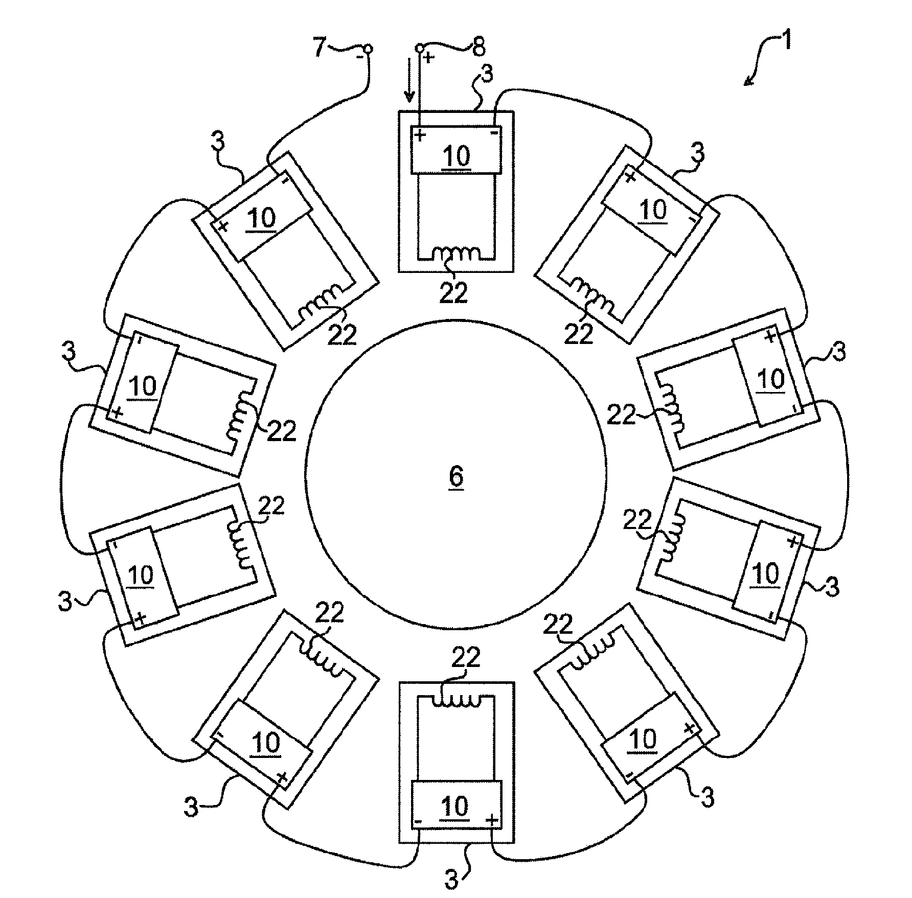
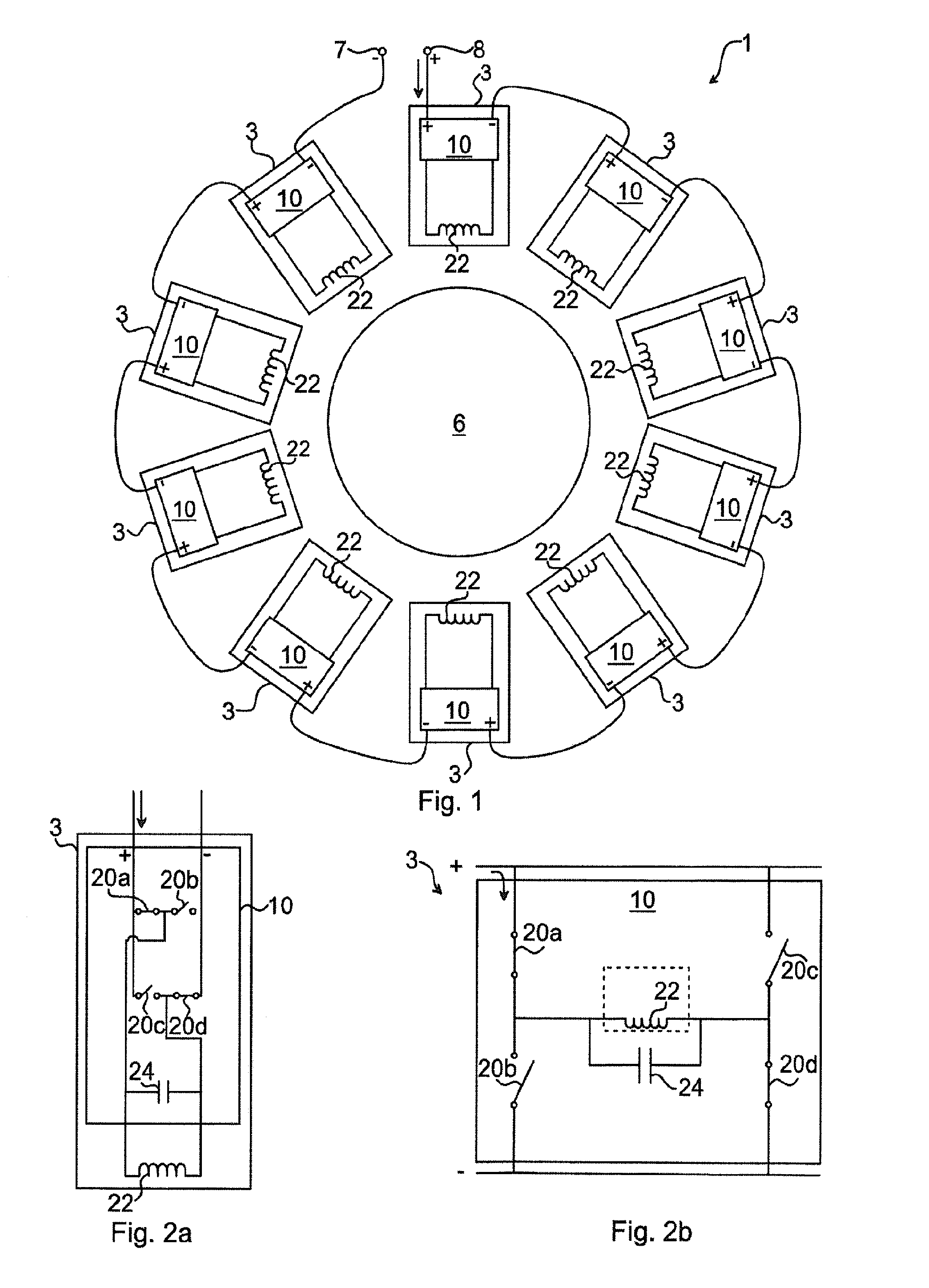
[0035]A rotating electrical machine 1, such as a synchronous electrical machine, comprises a stator and a rotor 6. In the case that the rotating electrical machine is a synchronous electrical machine, the machine can be of permanent magnet or electrical excitation type. Examples of permanent magnets that can be used are NdFeB or ferrite, or based on alloys of Cobalt (Co). The rotating electrical machine 1 can be a motor or generator...


PUM


Abstract

A rotating electrical machine including a stator or rotor including a plurality of serially connected switching cells. Each switching cell includes a winding subsection and a current reverser arranged to controllably alter a current direction through the winding subsection, and each current reverser includes a capacitor arranged to form a resonant circuit in cooperation with the winding subsection.

Description

FIELD OF THE INVENTION [0001]The invention relates to a rotating electrical machine and method for altering a current flowing in windings of such a rotating electrical machine.BACKGROUND OF THE INVENTION [0002]Currently, the market for the high power, medium voltage drive has been dominated by the AC (Alternating Current) drives, where the multi-level topology is used to produce the near-sinusoidal waveforms. DC (Direct Current) machines and synchronous machines are starting to increase in popularity as it provides other advantages.[0003]WO2006 / 100420 A1 presents an electrical machine such as a brushless dc rotating or linear machine. The electrical machine includes a first electronic commutator and a first stator winding including a number of coils linked by the same number of points of common coupling, each point of common coupling being connected to the first electronic commutator. The electrical machine also includes a second electronic commutator and a second stator winding inc...

Claims


Application Information

Patent Timeline
IPC IPC(8): H02K11/00
CPCH02P6/085H02K11/0073H02K11/33
Inventor LIU, YUJINGTENCA, PIERLUIGI
Owner ABB (SCHWEIZ) AG
Why Eureka
Try Eureka