Magnetic Logic Units Configured to Measure Magnetic Field Direction

a logic unit and magnetic field technology, applied in the direction of magnetic measurement, electrical/magnetically converting sensor output, instruments, etc., can solve the problem of cost-intensive amplification of earth's magnetic field

Active Publication Date: 2013-09-19
CROCUS TECHNOLOGY
View PDF5 Cites 41 Cited by
  • Summary
  • Abstract
  • Description
  • Claims
  • Application Information

AI Technical Summary

Problems solved by technology

This amplification of the Earth's magnetic field can be costly.

Method used


Image

  • Magnetic Logic Units Configured to Measure Magnetic Field Direction
  • Magnetic Logic Units Configured to Measure Magnetic Field Direction
  • Magnetic Logic Units Configured to Measure Magnetic Field Direction

Examples


Embodiment Construction

Definitions

[0025]The following definitions apply to some of the aspects described with respect to some embodiments of the invention. These definitions may likewise be expanded upon herein.

[0026]As used herein, the singular terms “a,”“an,” and “the” include plural referents unless the context clearly dictates otherwise. Thus, for example, reference to an object can include multiple objects unless the context clearly dictates otherwise.

[0027]As used herein, the term “set” refers to a collection of one or more objects. Thus, for example, a set of objects can include a single object or multiple objects. Objects of a set also can be referred to as members of the set. Objects of a set can be the same or different. In some instances, objects of a set can share one or more common characteristics.

[0028]As used herein, the terms “substantially” and “substantial” refer to a considerable degree or extent. When used in conjunction with an event or circumstance, the terms can refer to instances i...


PUM


Abstract

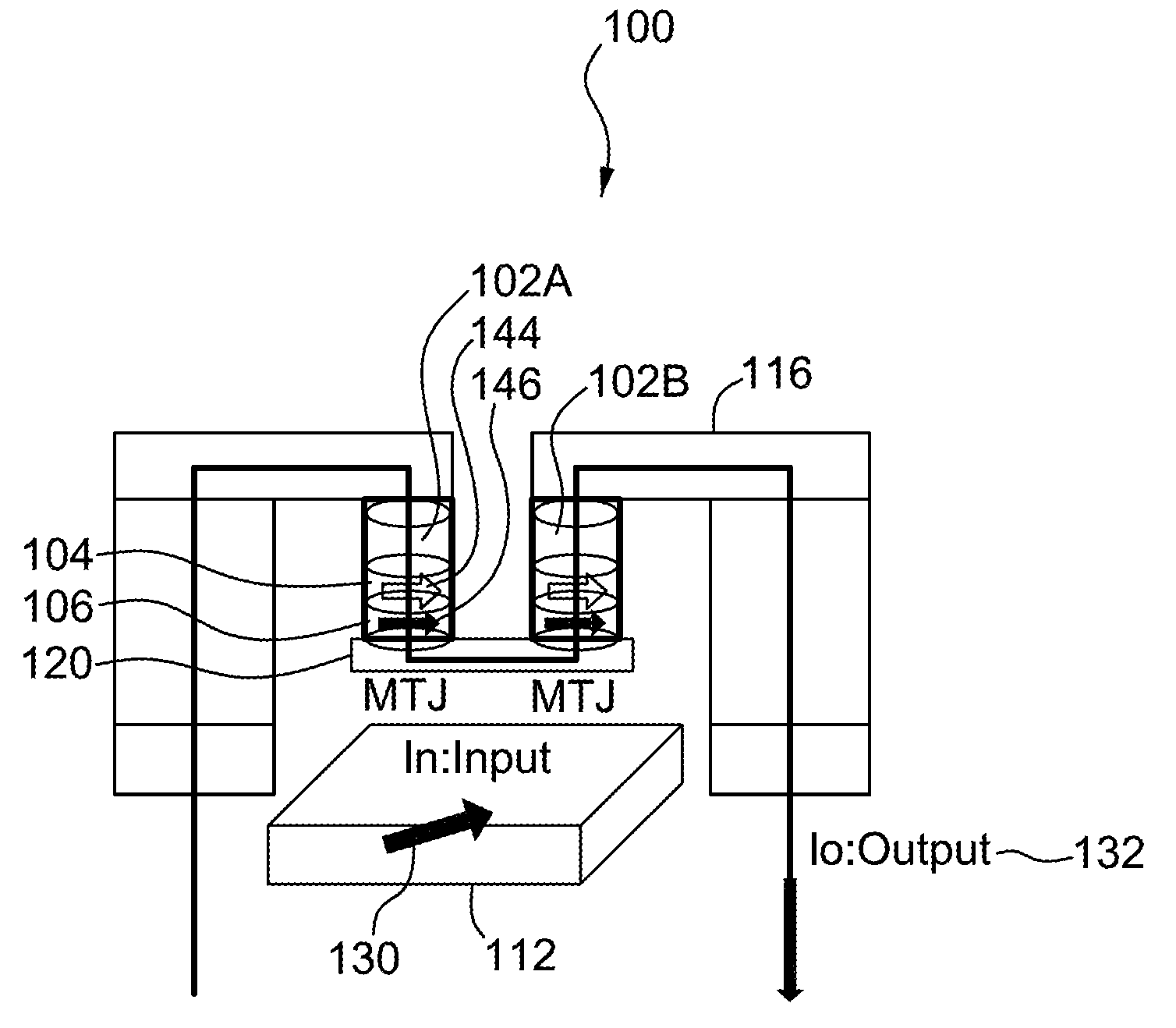
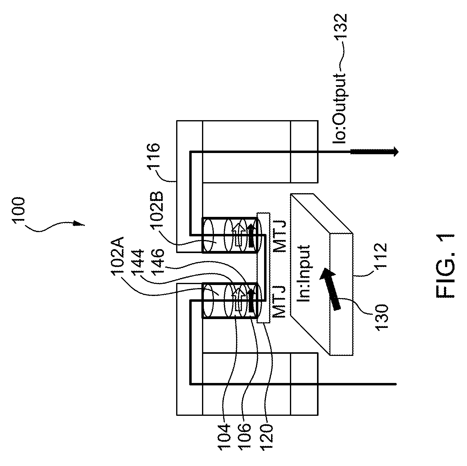
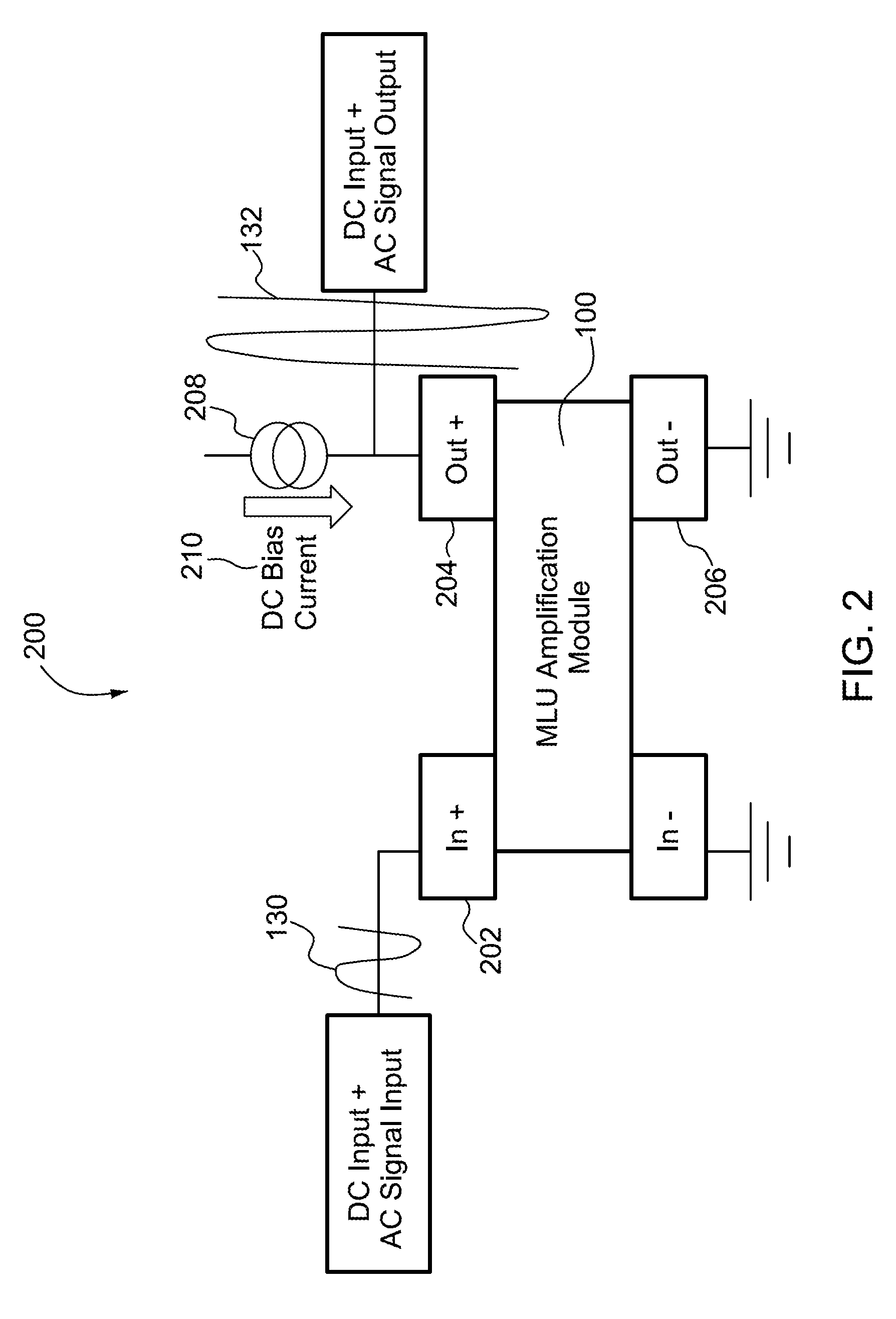
An apparatus includes circuits, a field line configured to generate a magnetic field based on an input, a sensing module configured to determine a parameter of each circuit, and a magnetic field direction determination module configured to determine an angular orientation of the apparatus relative to an external magnetic field based on the parameter. Each circuit includes multiple magnetic tunnel junctions. Each magnetic tunnel junction includes a storage layer having a storage magnetization direction and a sense layer having a sense magnetization direction configured based on the magnetic field. Each magnetic tunnel junction is configured such that the sense magnetization direction and a resistance of the magnetic tunnel junction vary based on the external magnetic field. The parameter varies based on the resistances of the multiple magnetic tunnel junctions. The magnetic field direction determination module is implemented in at least one of a memory or a processing device.

Description

CROSS-REFERENCE TO RELATED APPLICATION[0001]The present application claims the benefit of U.S. Provisional Application No. 61 / 608,015, filed on Mar. 7, 2012, the disclosure of which is incorporated herein by reference in its entirety.FIELD OF THE INVENTION[0002]The invention relates generally to magnetic logic units and, more particularly, to magnetic logic units configured to measure magnetic field direction.BACKGROUND[0003]The Earth's magnetic field is relatively small, with an average value on the order of 0.5 Oersted (Oe). In some devices, detecting the direction of the Earth's magnetic field is performed by first amplifying received magnetic fields using a magnetic field amplifier, locating the Earth's magnetic field, and determining the direction of the Earth's magnetic field. This amplification of the Earth's magnetic field can be costly. In addition, the magnetic field amplifier and other associated magnetics may be relatively large, which can result in compasses and / or magn...

Claims


Application Information

Patent Timeline
Patent Type & Authority Applications(United States)
IPC IPC(8): G01B7/30
CPCG01R33/096G01B7/30G01D5/16G01D5/12G01R33/098G01C17/02G01R33/0029G11C11/1659G11C11/1675G11C11/1673
Inventor CAMBOU, BERTRAND F.LEE, DOUGLAS J.MACKAY, KENHOBERMAN, BARRY
Owner CROCUS TECHNOLOGY
Why Eureka
Try Eureka