Lens-holder with offset hook

a technology of lens holder and offset hook, which is applied in the direction of mounting, flexible article cleaning, optics, etc., can solve the problems of not being able to perform transmission and grazing incidence light analysis, and achieve the effect of constant alignment position

Active Publication Date: 2013-09-19
SCL INT SPECIAL COATING LAB
View PDF1 Cites 4 Cited by
  • Summary
  • Abstract
  • Description
  • Claims
  • Application Information

AI Technical Summary

Benefits of technology

[0025]This arrangement makes it possible to preserve a relatively constant alignment position for the analysis device apparatuses despite the use of thicker and therefore heavier optical lenses.

Problems solved by technology

However, this lens-holder device, through the configuration of its body, does not make it possible to perform transmission and grazing incidence light analysis.

Method used


Image

  • Lens-holder with offset hook
  • Lens-holder with offset hook
  • Lens-holder with offset hook

Examples


Embodiment Construction

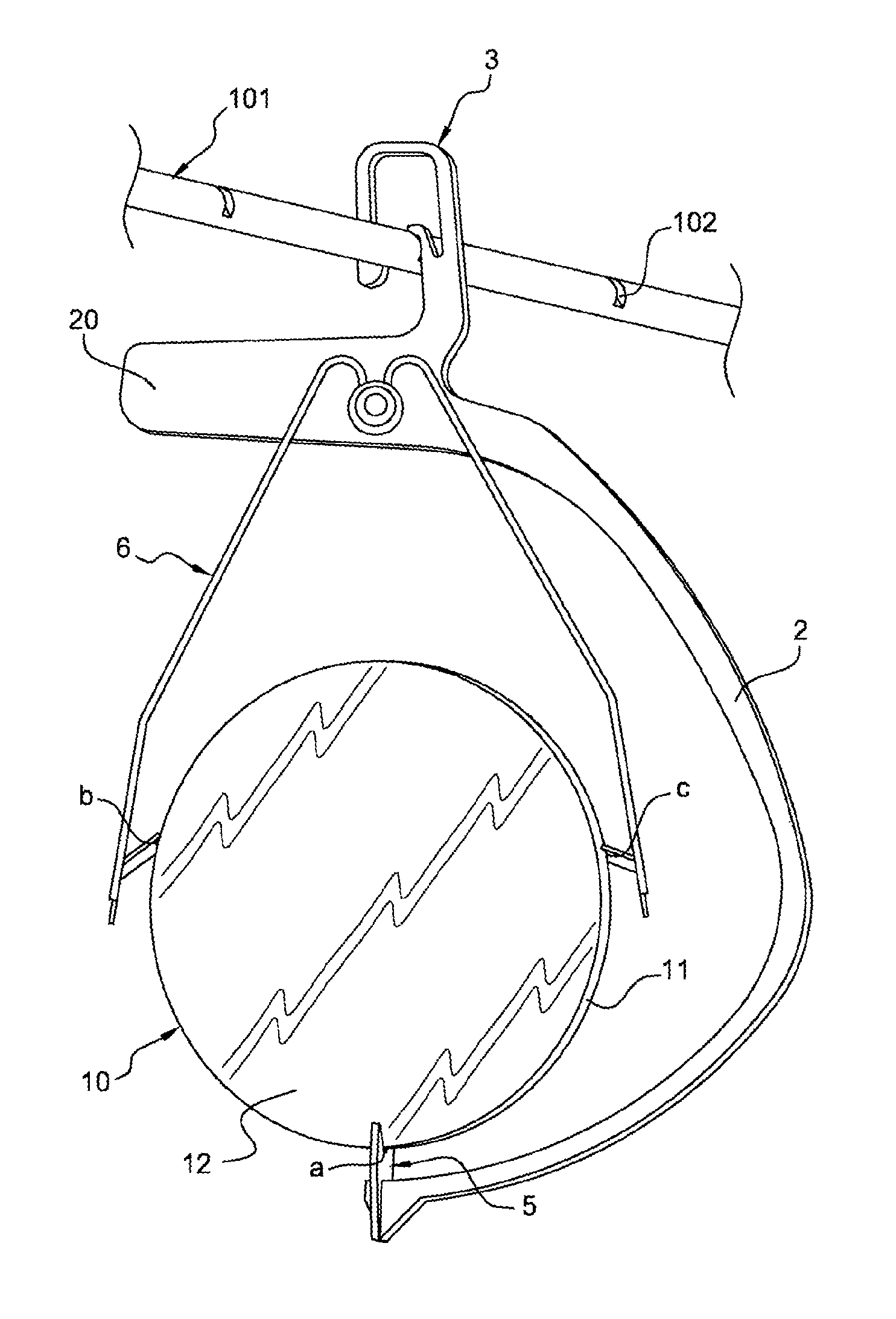
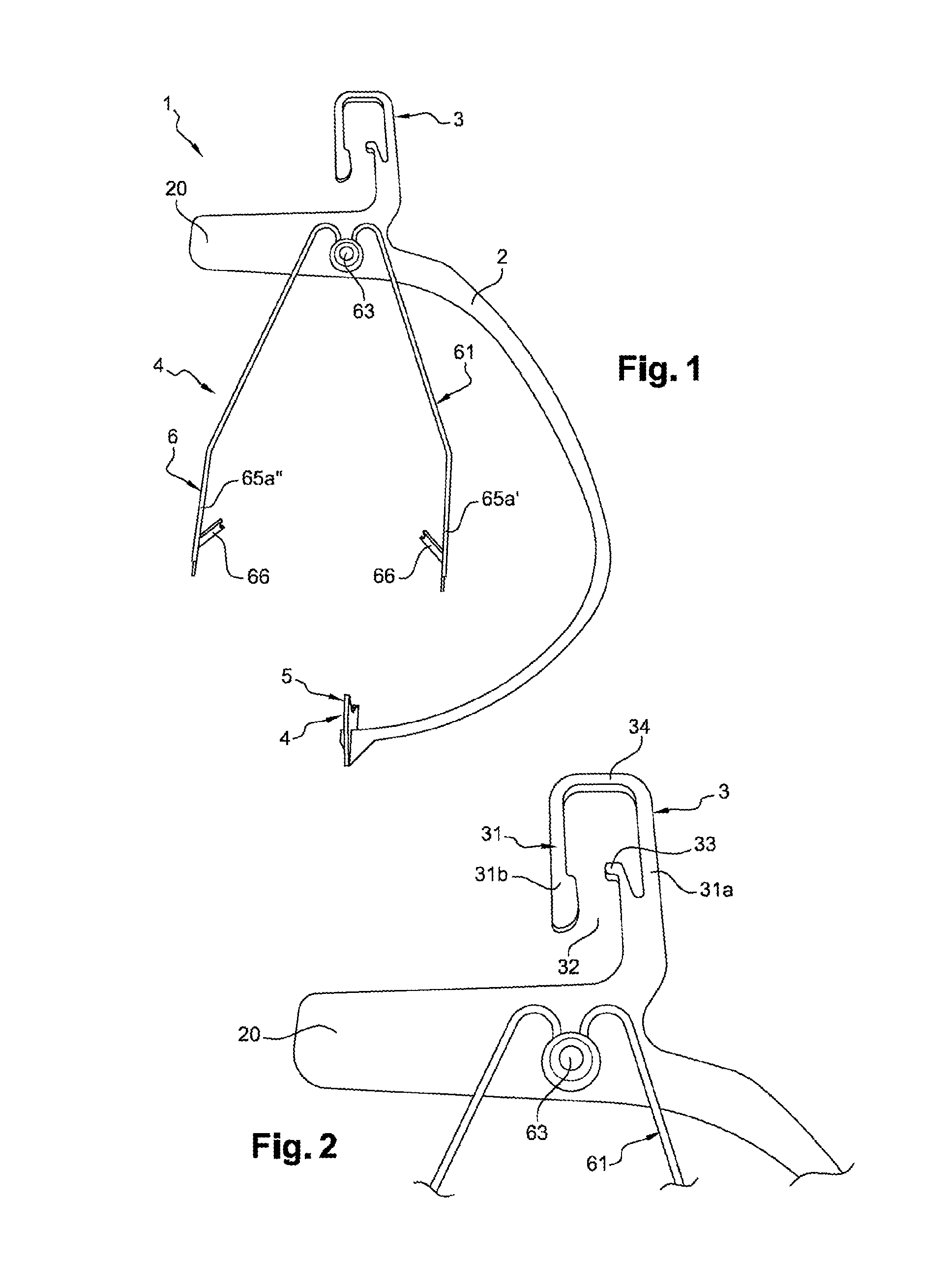
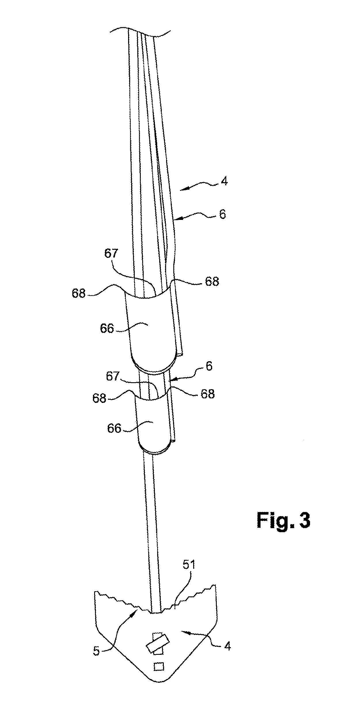
[0033]As illustrated in FIG. 1, a lens-holder device 1 according to one embodiment of the invention includes a body 2, also called a hook, to which suspension elements 3 are connected for the lens-holder device 1, in particular to a support 101 embodied by a rectilinear chassis bar 101 of the conveyor carriage, and retaining parts 4 for keeping the optical lens 10 in position.

[0034]The body 2 is rigid and does not deform under the action of the weight of an optical lens 10.

[0035]The suspension elements 3 of a lens-holder device 1 are connected to a first end of the body 2 and form a catch in the shape of an upside down U including two branches 31a, 31b and an opening 32.

[0036]The opening 32 created between the branches 31a, 31b of the catch 31 is designed to receive the chassis bar 101 of a conveyor carriage that is gripped between part of the branches 31a, 31b, one of which 31a has a rectilinear profile that is engaged in a notch 102 whereof the bottom is also rectilinear, the bloc...


PUM


Abstract

The subject of the present invention is a lens-holder device (1) intended to be hooked onto a support (101) of determined direction belonging to a conveyor carriage intended for transporting optical lenses (10) so that an optical test can be carried out on said optical lenses following a treatment of said optical lenses, said lens-holder device (1) comprising a body (2), suspension means (3) for suspending from the support (101) which are connected to the body (2), retaining the means (4) for keeping an optical lens (10) in position on the lens-holder device (1), which are connected to the body (2), these retaining means (4) comprising support means (5) defining at least one first resting point (a) for the optical lens (10), elastic return means (6) defining at least two further resting points (b, c) for the optical lens (10), the various resting points (a, b, c) defining a location for the optical lens (10), the body of the lens-holder device (1) being shaped in such a way as to pass around the portions of space that are situated facing the location occupied by the optical lens (10).

Description

TECHNICAL FIELD[0001]The present invention relates to a lens-holder device more particularly designed for the analysis of optical lenses.BACKGROUND[0002]A lens-holder device may typically be hooked to a holder of a conveyor carriage of an analysis machine, said conveyor carriage being designed to transport optical lenses so that an optical test can be carried out on said optical lenses following a treatment of said optical lenses.[0003]These treatments may be of various types, for example such as chemical strengthening, thermal strengthening or treatments providing abrasion resistance, anti-scratch-treatments, antireflective treatments, anti-soiling treatments, ultraviolet treatments, or tinting treatments.[0004]The analyses done may also be of several types, in particular reflection, transmission, or grazing incidence light.[0005]To be able to perform these analyses, it is preferable to keep a same location for an optical lens over time and for optical lenses of different weights s...

Claims


Application Information

Patent Timeline
Patent Type & Authority Applications(United States)
IPC IPC(8): G02B7/02
CPCB05C13/02B08B11/02B05C3/09G02B7/02B29D11/00432B29D11/00
Inventor GEHRIG, JEANGEHRIG, DENIS
Owner SCL INT SPECIAL COATING LAB
Why Eureka
Try Eureka