Electronic device

a technology of electronic devices and flat-line cables, which is applied in the direction of electrical apparatus contruction details, electrical apparatus casings/cabinets/drawers, printed circuit non-printed electric components association, etc., can solve the problem of increasing the radiated electromagnetic noise of communication cables, and increasing the manufacturing cost of flexible flat-line cables. problem, to achieve the effect of suppressing the radiated electromagnetic noise of flexible flat-line cables

Inactive Publication Date: 2013-09-19
PANASONIC INTELLECTUAL PROPERTY MANAGEMENT CO LTD
View PDF8 Cites 9 Cited by
  • Summary
  • Abstract
  • Description
  • Claims
  • Application Information

AI Technical Summary

Benefits of technology

[0011]However, providing a metal shield layer in a flexible flat cable causes an increase in manufacturing cost of the flexible flat cable.
[0013]Accordingly, an object of the present disclosure is to provide an electronic device capable of suppressing radiation of electromagnetic noise from flexible cables.
[0015]According to the electronic device of this disclosure, since the characteristic impedance of the flexible cable within the electronic device is successfully matched, radiation of electromagnetic noise from the flexible flat cable can be suppressed.

Problems solved by technology

As digital signals transmitted in digital interfaces (communication cables) become higher and higher in speed, electromagnetic noise radiated from the communication cables increases more and more.
Therefore, in a case where, for example, a flexible flat cable is partly floated in the air while its rest is fixed to the chassis, the characteristic impedance of the flexible flat cable breaks down, and it becomes hard to take a matching with a characteristic impedance of a connection-destined transmission path element.
However, providing a metal shield layer in a flexible flat cable causes an increase in manufacturing cost of the flexible flat cable.
As a result, increases in electromagnetic noise radiated from the flexible flat cable may occur.

Method used


Image

  • Electronic device
  • Electronic device
  • Electronic device

Examples


embodiment 1

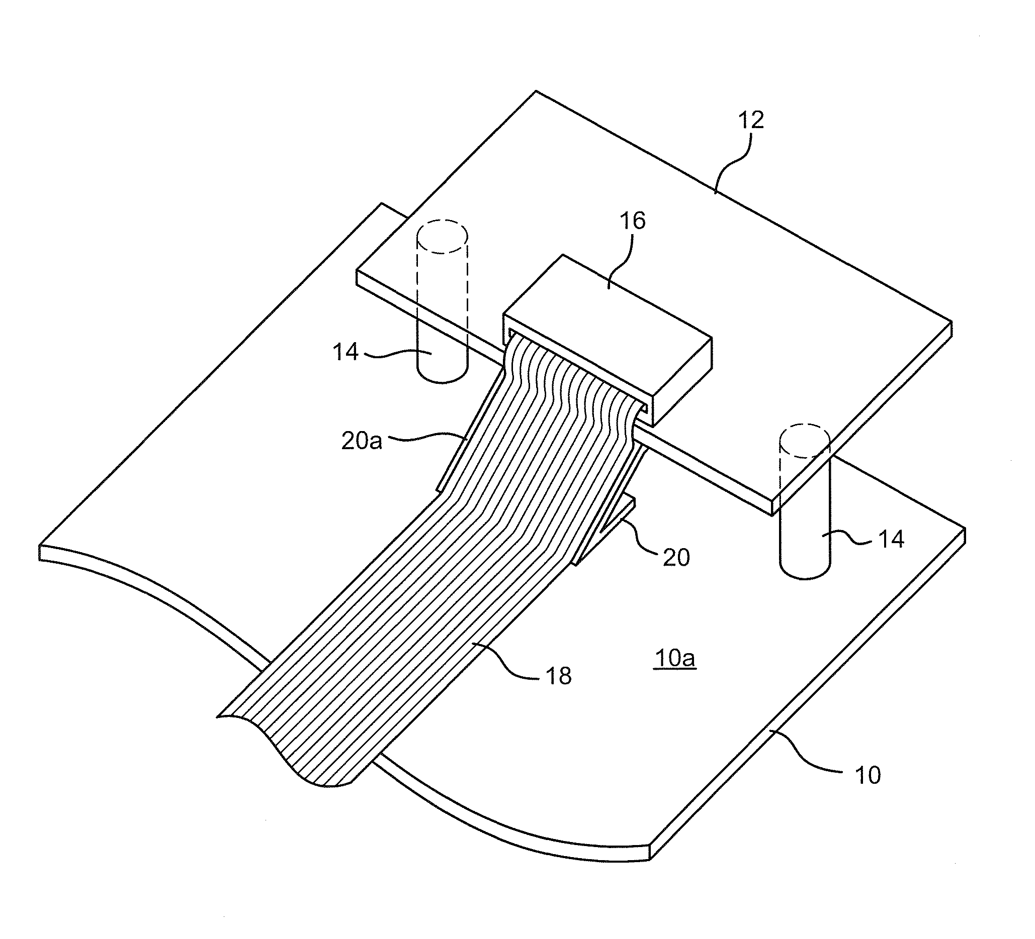
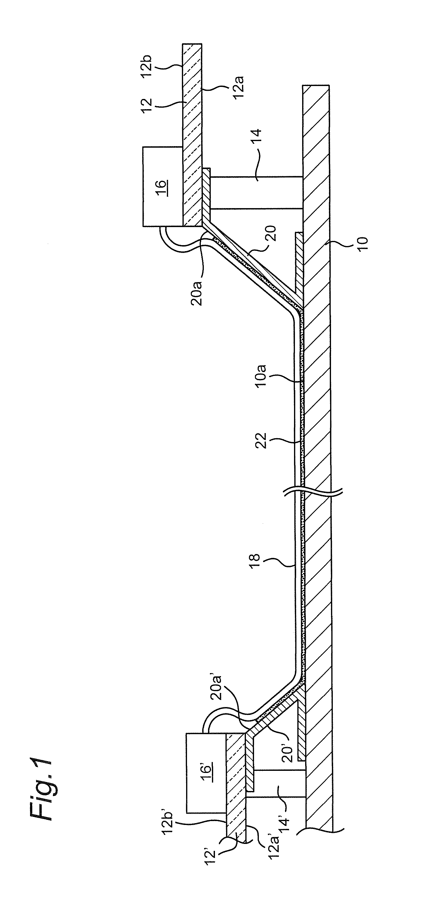
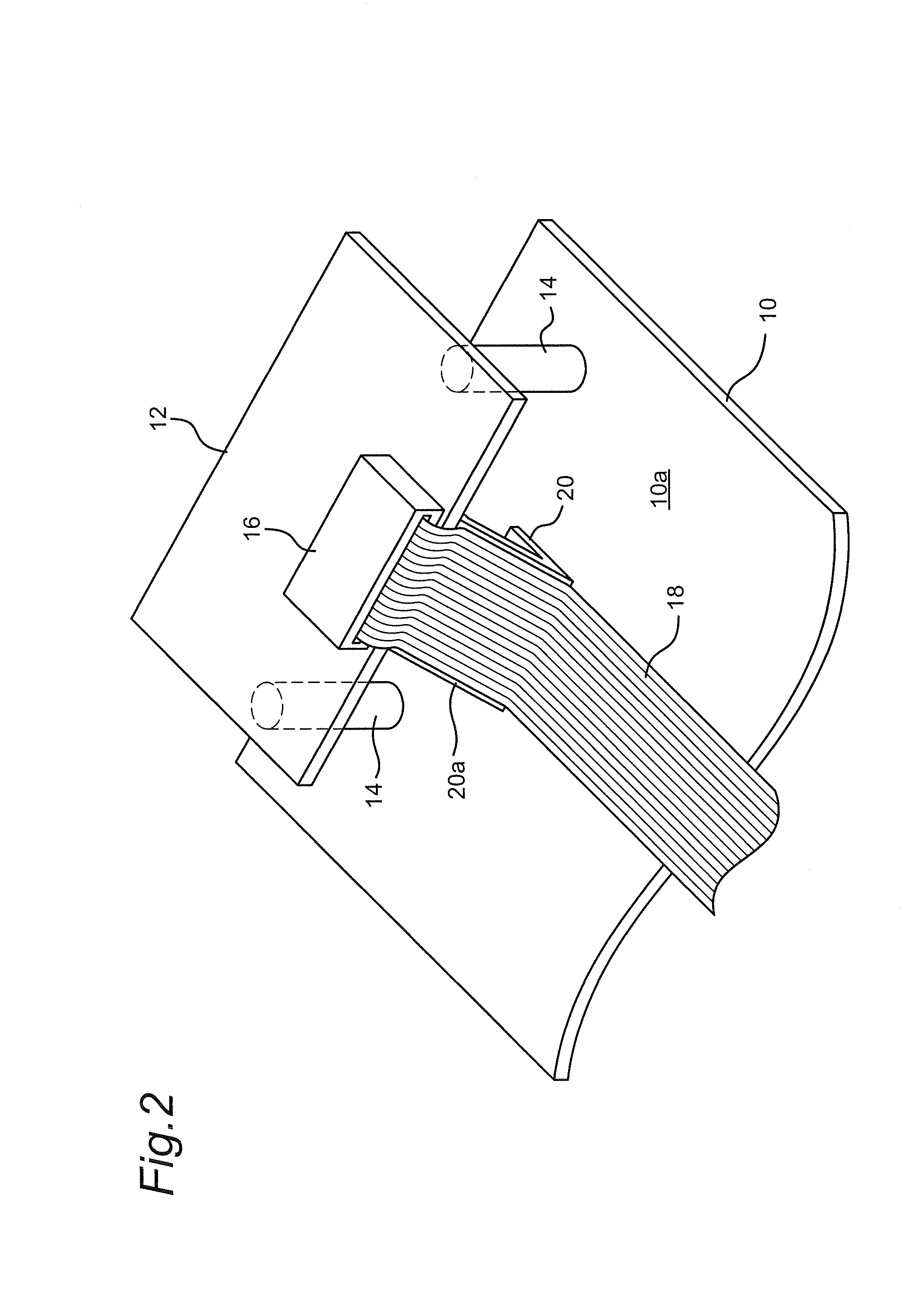
[0033]FIG. 1 is a sectional view schematically showing an electronic device according to Embodiment 1. The electronic device of this Embodiment 1 is a television, as an example, which internally has a conductor plate (chassis) 10 made from an electroconductive material (e.g., metal), and a plurality of circuit boards 12, 12′. The circuit boards 12, 12′ are placed so as to be spaced from a surface 10a of the chassis 10 via spacers 14, 14′ and moreover fixed to the chassis 10. In addition, the chassis 10 is grounded.

[0034]The circuit boards 12, 12′ have connectors 16, 16′ for interchanging signals to each other. More specifically, the connectors 16, 16′ are provided at edges of surfaces 12b, 12b′ of the circuit boards 12, 12′ on one side thereof counter to their surfaces 12a, 12a′ facing the surface 10a of the chassis 10, respectively.

[0035]For interchanging of signals between the circuit boards 12, 12′, one end of a flexible flat cable 18 is connected to the connector 16 of the circu...

embodiment 2

[0058]Embodiment 2 differs from Embodiment 1 in that the portion of the flexible flat cable 18 ranging from the connector 16 to the surface 10a of the chassis 10 is held by part of the chassis 10. Therefore, this Embodiment 2 will be described below mainly about those difference points from Embodiment 1.

[0059]FIG. 4 is a sectional view schematically showing an electronic device according to Embodiment 2. FIG. 5 is a schematic perspective view showing a portion of a flexible flat cable 18 placed between a circuit board 12 and a chassis 10.

[0060]As shown in FIGS. 4 and 5, a cable holding part 10b for holding a portion of the flexible flat cable 18 ranging from the connector 16 to the surface 10a of the chassis 10 is formed in the chassis 10. The cable holding part 10b includes a sloped holding surface 10c for holding the flexible flat cable 18 via the adhesive member 22.

[0061]The cable holding part 10b is formed by, for example, forming a bracket (square bracket)-shaped cut-in in the ...

embodiment 3

[0065]Embodiment 3 differs from Embodiment 1 in the method of electrical connection between the cable holding member and the chassis. Therefore, this Embodiment 3 will be described mainly about this difference point from Embodiment 1.

[0066]FIG. 6 is a sectional view schematically showing an electronic device according to this Embodiment 3. FIG. 7 is a schematic perspective view showing a portion of the flexible flat cable 18 placed between the circuit board 12 and the chassis 10.

[0067]As shown in FIGS. 6 and 7, a cable holding member 24 includes a holding surface 24a for holding a portion of the flexible flat cable 18 ranging from the connector 16 of the circuit board 12 to the surface 10a of the chassis 10, and a base portion 24b to be electrically connected and fixed to the chassis 10. The base portion 24b of the cable holding member 24 is electrically connected and fixed to the chassis 10 with metal screws 26. The flexible flat cable 18 is fixed to the holding surface 24a and the...


PUM


Abstract

An electronic device includes a conductor plate, a circuit board placed with a distance to a surface of the conductor plate, a connector provided on the circuit board, a flexible cable having one end connected to the connector and laid down along the surface of the conductor plate, and a cable holding member which includes a sloped holding surface for holding at least part of a portion of the flexible cable ranging from the connector to the surface of the conductor plate and which is electrically connected to the conductor plate.

Description

CROSS-REFERENCE TO RELATED APPLICATIONS[0001]This is a continuation application of International Application No. PCT / JP2012 / 006400, with an international filing date of Oct. 4, 2012, which claims priority of Japanese Patent Application NO.: 2011-247622 filed on Nov. 11, 2011, the content of which is incorporated herein by reference.BACKGROUND OF THE INVENTION[0002]1. Technical Field[0003]The present disclosure relates to an electronic device having a flexible cable and contrived so that electromagnetic noise derived from the flexible cables is reduced.[0004]2. Description of Related Art[0005]In recent years, digital interfaces serving for interconnecting one electronic device to another, or provided within electronic devices have been advanced toward increasingly higher speeds. For example, high-speed serial interfaces using differential signals, such as LVDS (Low Voltage Differential Signaling), HDMI (High-Definition Multimedia Interface) and USB (Universal Serial Bus), are used in...

Claims


Application Information

Patent Timeline
Patent Type & Authority Applications(United States)
IPC IPC(8): H05K1/02H05K1/14
CPCH05K1/0218H05K1/0277H05K1/14H05K2201/10356H05K1/025H05K2201/2036H05K1/147H05K2201/10189H05K2201/10371H05K2201/2009H05K1/0281
Inventor MASUDA, KOHEISHIBATA, OSAMUSAITO, YOSHIYUKI
Owner PANASONIC INTELLECTUAL PROPERTY MANAGEMENT CO LTD
Why Eureka
Try Eureka