Cervical dilator

a cervical dilator and dilation device technology, applied in the direction of dilatation devices, balloon catheters, surgery, etc., can solve the problems of increasing the risk of infection or the creation of unintended false passages in the uterine fundus, and the inherently risky use of instruments such as dilatation devices by the physician, so as to improve the effect of cervical dilators

Inactive Publication Date: 2013-09-19
GYNEKARE
View PDF5 Cites 5 Cited by
  • Summary
  • Abstract
  • Description
  • Claims
  • Application Information

AI Technical Summary

Benefits of technology

[0021]One advantage of the present invention may be that it provides for an improved cervical dilator.
[0022]A further advantage of the present invention may be that it provides for an improved cervical dilator that is made of sterilized plastic or metal components that creates a one time use instrument, thus ensuring sterilization of the cervical dilator.
[0023]Still a further advantage of the present invention may be that it provides for a cervical dilator that has custom fitting via the use of flexible materials.
[0024]Still a further advantage of the present invention may be that it provides for a cervical dilator that uses balloon technology and a warm saline infusion to dilate the cervix of the patient.
[0025]Still another advantage of the present invention may be that it provides for a cervical dilator that has graduated and ratcheted inflation capabilities, thus allowing only one instrument as opposed to the prior art six to dilate the cervix and uterus to the proper diameter. This also creates only one insertion by the physician as opposed to twelve via the prior art dilation methodology.
[0026]Still another advantage of the present invention may be that it provides for a cervical dilator that has the ability to measure the uterine length, thus avoiding a thirteenth insertion such as that done in prior art to determine such length.

Problems solved by technology

However, the use of these dilator sets presents several technological constraints to the physician using such instruments.
The Hanks dilators are rigid instruments that inherently risk damage to the cervix, uterus, bowel bladder and major blood vessels by puncture or perforation.
The use of the Hanks dilators also creates an excessive number of passes or insertions, in most cases twelve, to fully dilate the cervix, thus increasing the risk associated with infection or the creation of unintended false passages within the uterine fundus.
Furthermore, the use of the Hanks dilators and the current one size fits all approach does not customize to the individual patient's cervical length.
Additionally, a twelve step process may introduce potential human error via incorrect packaging of instruments, possible out of sequence handling or insertion by the doctor or by assistants or nurses assisting during the procedure.
With each insertion of the prior art dilators the risk of such potential perforations increases, thus increasing the risk to the patient having the procedure performed thereon.
Another risk associated with using prior art metal dilators is that human error may occur in the packaging of and the sterilization of the instruments offered to the physician during the procedure.
With each of the dilators increasing by a small percentage in diameter, the possibility of receiving a dilator in an improper order occurs.

Method used


Image

  • Cervical dilator
  • Cervical dilator
  • Cervical dilator

Examples


Embodiment Construction

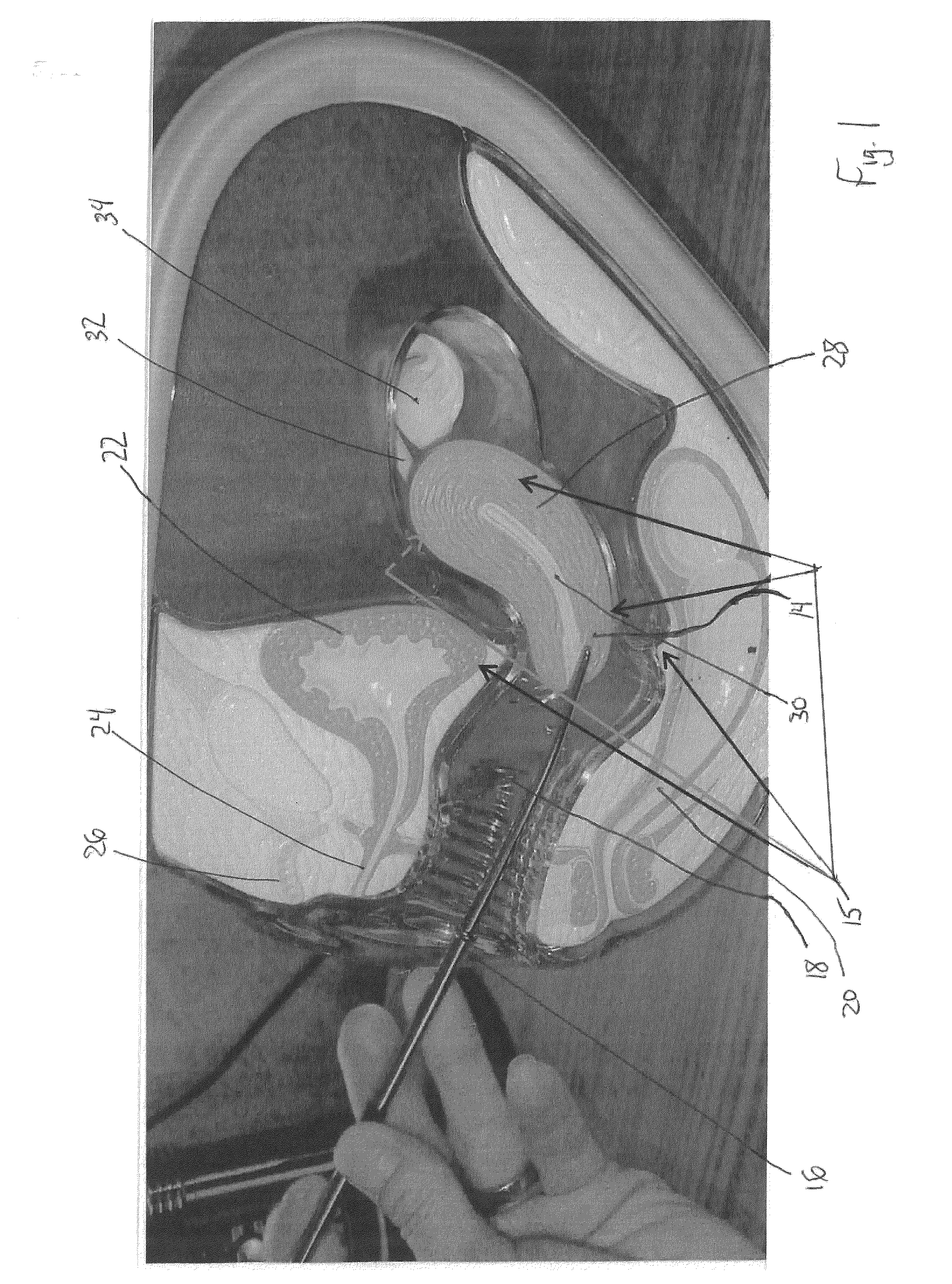
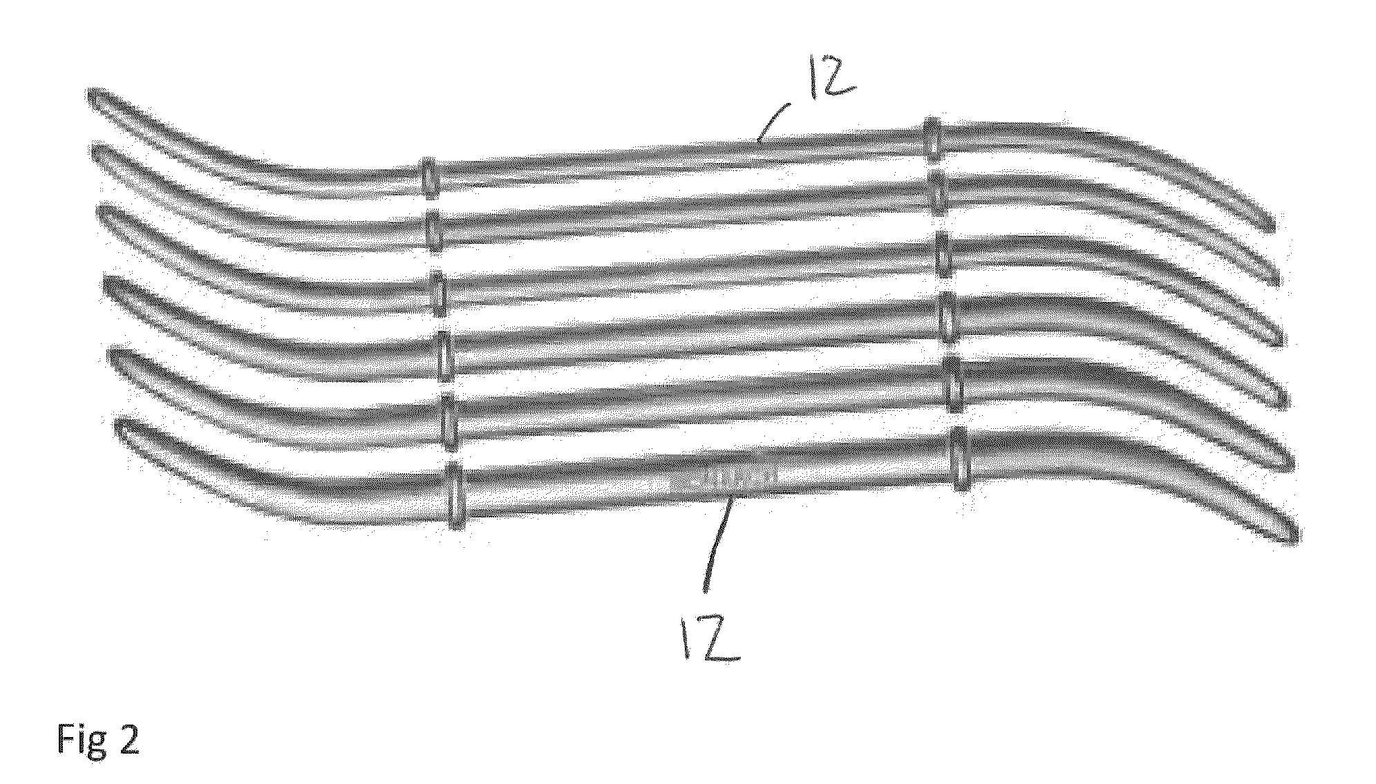
[0043]Referring to the drawings, there is shown a cervical dilator 10 according to an embodiment of the present invention. The drawings also show an associated methodology for use in dilating a cervix of a patient with the cervical dilator 10 of the present invention. FIG. 1 shows a cross section of a female pelvic anatomy having a prior art Hanks dilator 12 inserted into the cervix 14. Generally, the female pelvic anatomy includes the labia 16, which flanks the outside portion of a female vagina 18. The female vagina 18 is located directly adjacent to the labia 16 in the female pelvic anatomy. A female's rectum 20 and bladder 22 are arranged directly adjacent to the vagina 18 of the female. The bladder 22, urethra 24 and clitoris 26 are all arranged above the vagina 18 in a female, while the rectum 20 is arranged below the vagina 18 in the female pelvic anatomy. Arranged a variable distance within the vagina 18 is the cervix 14 and uterus 28. The uterus' front portion is commonly c...


PUM


Abstract

A cervical dilator for use in dilating a cervix comprises a light weight flexible tube member. The cervical dilator also comprises a syringe connected to a first end of the flexible tube member for introducing a liquid or air solution into the tube member. The cervical dilator also includes a balloon arranged over an end of the tube that is inserted into the cervix of the patient in an uninflated state. The cervical dilator also comprises at least one orifice arranged through or near an end of the flexible tube member and within the interior cavity of the balloon, such that the air or liquid inflates the balloon to a predetermined diameter.

Description

BACKGROUND OF THE INVENTION[0001]1. Field of the Invention[0002]The present invention generally relates to an instrument used for cervical dilation and more particularly relates to an improved cervical dilator that streamlines the surgical procedure of dilating a uterine cervix thus benefiting the patient, physician and surgical team in the operating environment.[0003]2. Description of Related Art[0004]Prior art cervical dilators, such as Hanks dilators, have been used by obstetrician / gynecologists (OB / GYNs) for many years. Generally, a Hanks dilator set is comprised of a set of six metal rods, each having a specific graduated diameter on each end thereof. The use of Hanks dilators to dilate a uterine cervix requires twelve insertions and twelve points of potential damage and infection to the patient during the process. Generally, when a women presents to a OB / GYN with abnormal uterine bleeding, her doctor is required to investigate the source of such uterine bleeding, in order to a...

Claims


Application Information

Patent Timeline
Patent Type & Authority Applications(United States)
IPC IPC(8): A61M29/02
CPCA61M29/02A61M2025/1093
Inventor NIVER, KAREN LOUISE
Owner GYNEKARE
Why Eureka
Try Eureka