However, these approaches are of limited utility and are generally not practiced due to harsh operating conditions that limit the ability to distribute locomotive functions across disparate chassis as well as the technical challenges of integrating stock railroad equipment with locomotives.
These static arrangements have failed due to the lack of operational flexibility required for day-to-day operation of locomotives and/or operational limitations (such as locomotive range, power production limitations, and requiring support for multiple fuel sources).
In particular, “genset” style locomotive controllers have not found use in line haul applications because they produce lower overall power than a single, large engine.
Use of dissimilar power source arrangements have failed due cost and operational issues.
Known locomotive controllers also fail to address unexpected signals and operational challenges that become evident when extending the locomotive control and power systems between disparate railcar chassis and integrating power from these external sources with power produced by the engine/generator(s) on the locomotive chassis.
As a result, many locomotive power tender configurations have been tried and abandoned due to a number of operational, safety, and related technical issues.
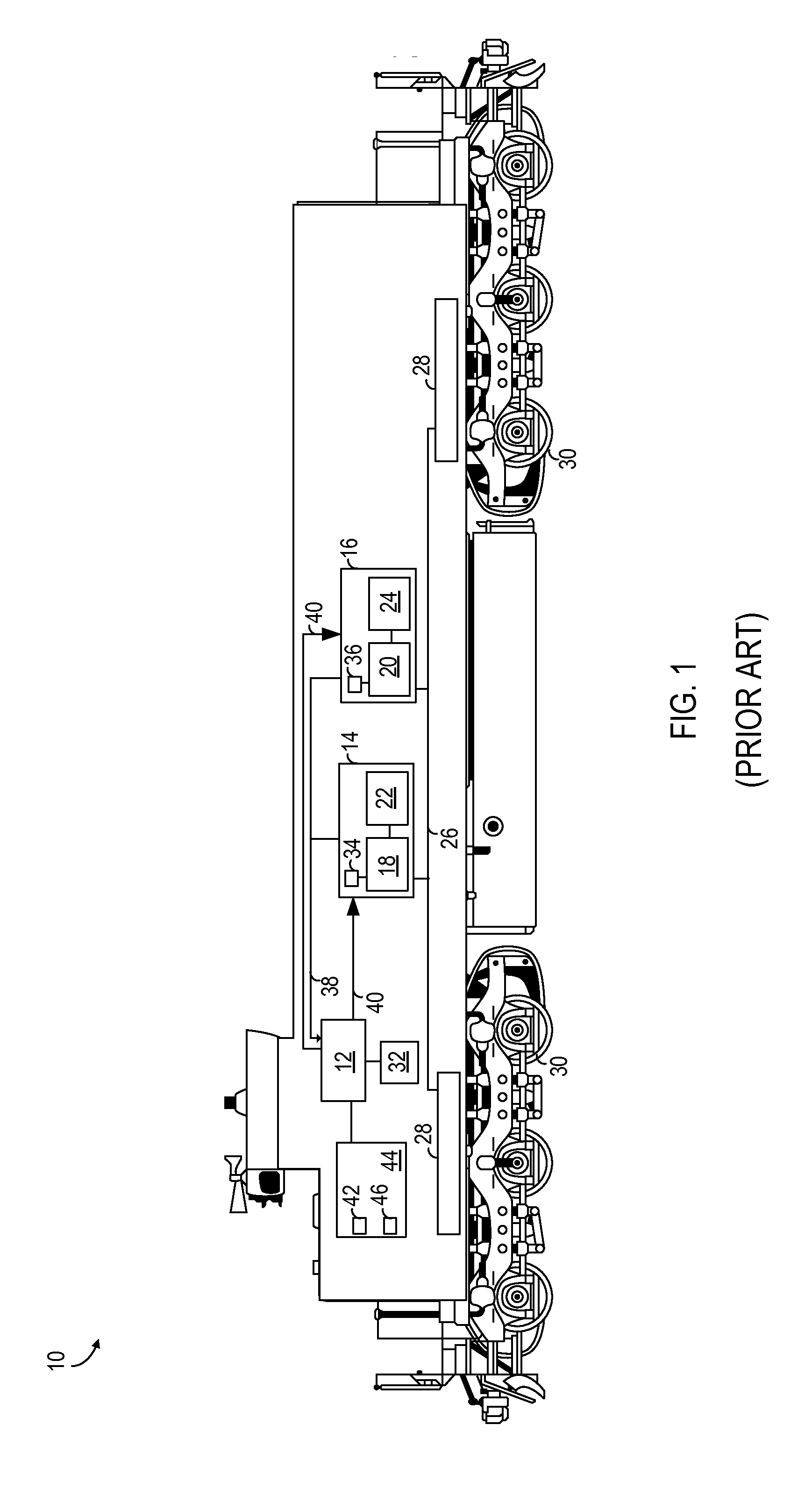
Each rail car is approximately 100 feet in length, and signal degradation, electro-magnetic interference, propagation delays, and related issues are factors when operating a power tender and locomotive together.
Second, extending the power bus (sometimes called a fraction bus) between railcars presents similar concerns, not with the signal degradation, but with the cabling and switching apparatus used to safely transport high amperage currents (e.g., 2000 amps) between the power tender and the locomotive fraction bus.
Power losses, in particular, voltage losses, arcing, and related issues come into play.
Since locomotive power blending is governed by the voltage of the provided power, and is characterized by tight control of the voltage provided to the power bus, losses in voltage or current between a power tender and the locomotive will cause the locomotive controller to improperly manage the combined locomotive/tender.
In some cases, these losses will cause the locomotive to not operate.
Third, locomotives and attached power tenders operate in harsh environments.
The physical challenges are many and varied; they include widely varied operating temperatures, weather, poor electrical connections between the locomotive and the tender, etc.
The control and sensor data is subject to intense electro-magnetic environments (that disrupts the control and sensor data) both external to the consist and within the infrastructure.
The shielding required to mitigate these issues described above is itself susceptible to the physical challenges, and degrades over time.
Operating a locomotive/power tender in these conditions is challenging.
Fourth, locomotives and their attached power tenders may encounter operational issues, such as connector failure, cable separation, or even chassis separation during regular operation (for example, as would be caused by a coupler failure).
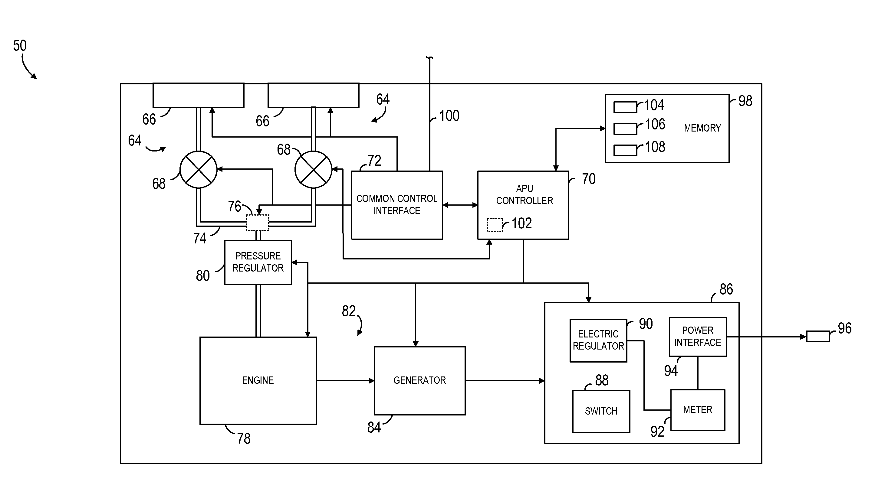
Given the complex nature of locomotive control and the interrelatedness of locomotive loads such as traction motors and blowers, a locomotive's controller, its engine-generator, and an external power tender cannot “share” the generation requirement, with a portion of the power coming from the engine-generator, and remainder of the power coming from the external power tender without the locomotive controller being aware of the power tender and the amount of power it produces.
Since other locomotive systems are often tied to the locomotive engine-generator or are utilized proportionally to the amount of power being used by locomotives loads (e.g., blowers, aux power), this results in a non-functioning loco

