
Shingled magnetic recording disk drive with inter-band disk cache and minimization of the effect of far track erasure on adjacent data bands

a magnetic recording and inter-band disk cache technology, applied in data recording, memory allocation/allocation/relocation, instruments, etc., can solve the problems of wide-area track erasure (water) or far track encroachment or erasure (fte), and the effect of reducing the effect of fte in the boundary region

Active Publication Date: 2013-09-19
WESTERN DIGITAL TECH INC
View PDF3 Cites 20 Cited by
  • Summary
  • Abstract
  • Description
  • Claims
  • Application Information

AI Technical Summary

Benefits of technology

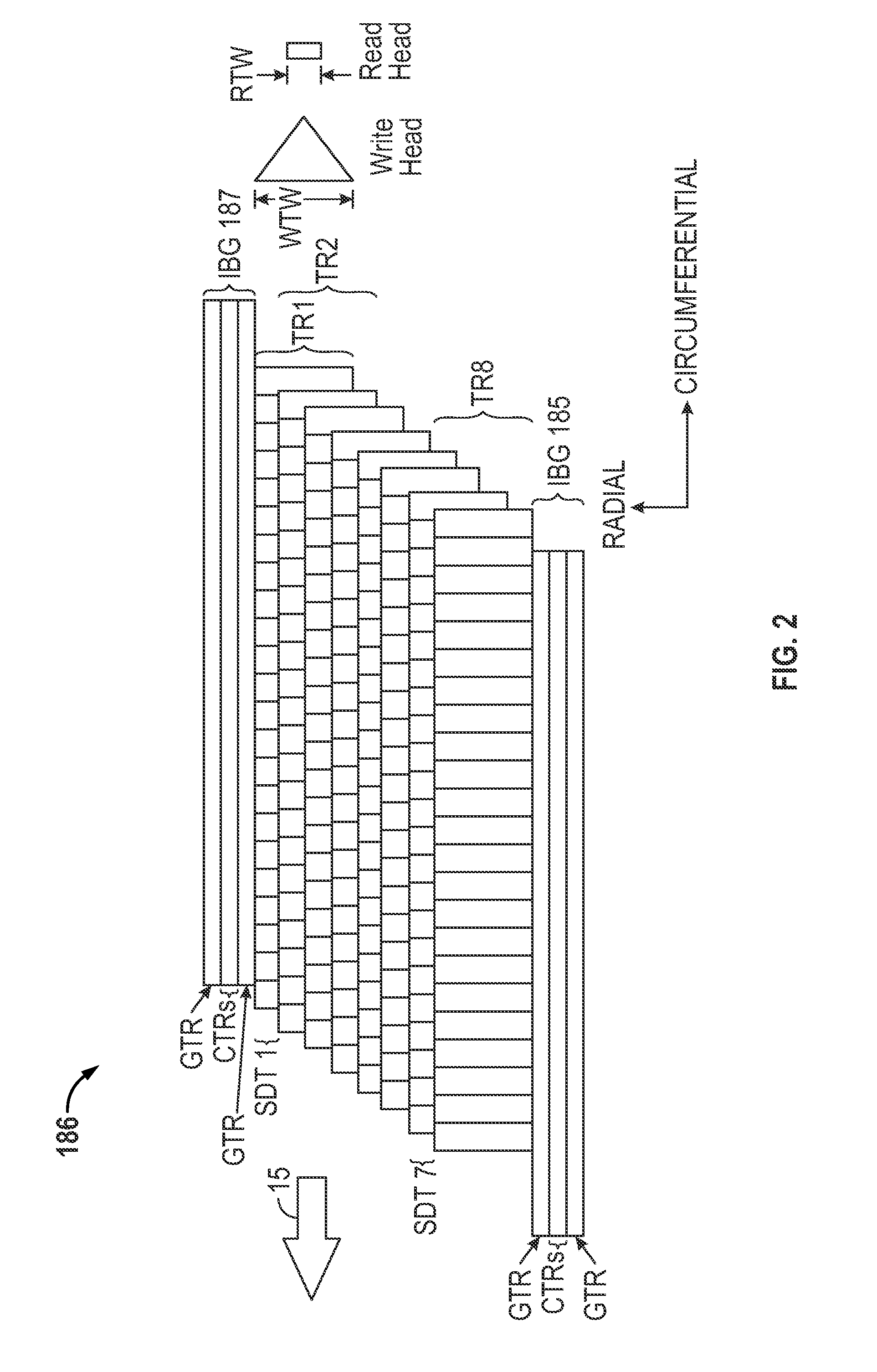
This patent relates to a way to improve the performance of a specific type of hard disk drive (HDD) called a SMR HDD. The invention involves using a cache in the form of writeable cache tracks in the inter-band gaps between the annular data bands. By minimizing the impact of FTE (Write Read Offset) in the boundary regions of the annular data bands caused by writing to the cache tracks, the invention aims to optimize data transfer and improve performance. The extent of the FTE effect is determined for each track within a range of tracks in the cache track being written. A count increment (CI) is determined for each track within a boundary region that is within a range of the cache track being written. When the count value for a track reaches a predetermined threshold, the data is read from the boundary region and rewritten to the same band. This process optimizes data transfer and reduces latency, resulting in improved performance of the SMR HDD.

Problems solved by technology

A problem in both conventional HDDs and SMR HDDs is wide-area track erasure (WATER) or far track encroachment or erasure (FTE).
Tracks on one side may encounter more pronounced FTE effects due to the write head shield design or due to read-write head skew.

Method used


Image

  • Shingled magnetic recording disk drive with inter-band disk cache and minimization of the effect of far track erasure on adjacent data bands
  • Shingled magnetic recording disk drive with inter-band disk cache and minimization of the effect of far track erasure on adjacent data bands
  • Shingled magnetic recording disk drive with inter-band disk cache and minimization of the effect of far track erasure on adjacent data bands

Examples


Embodiment Construction

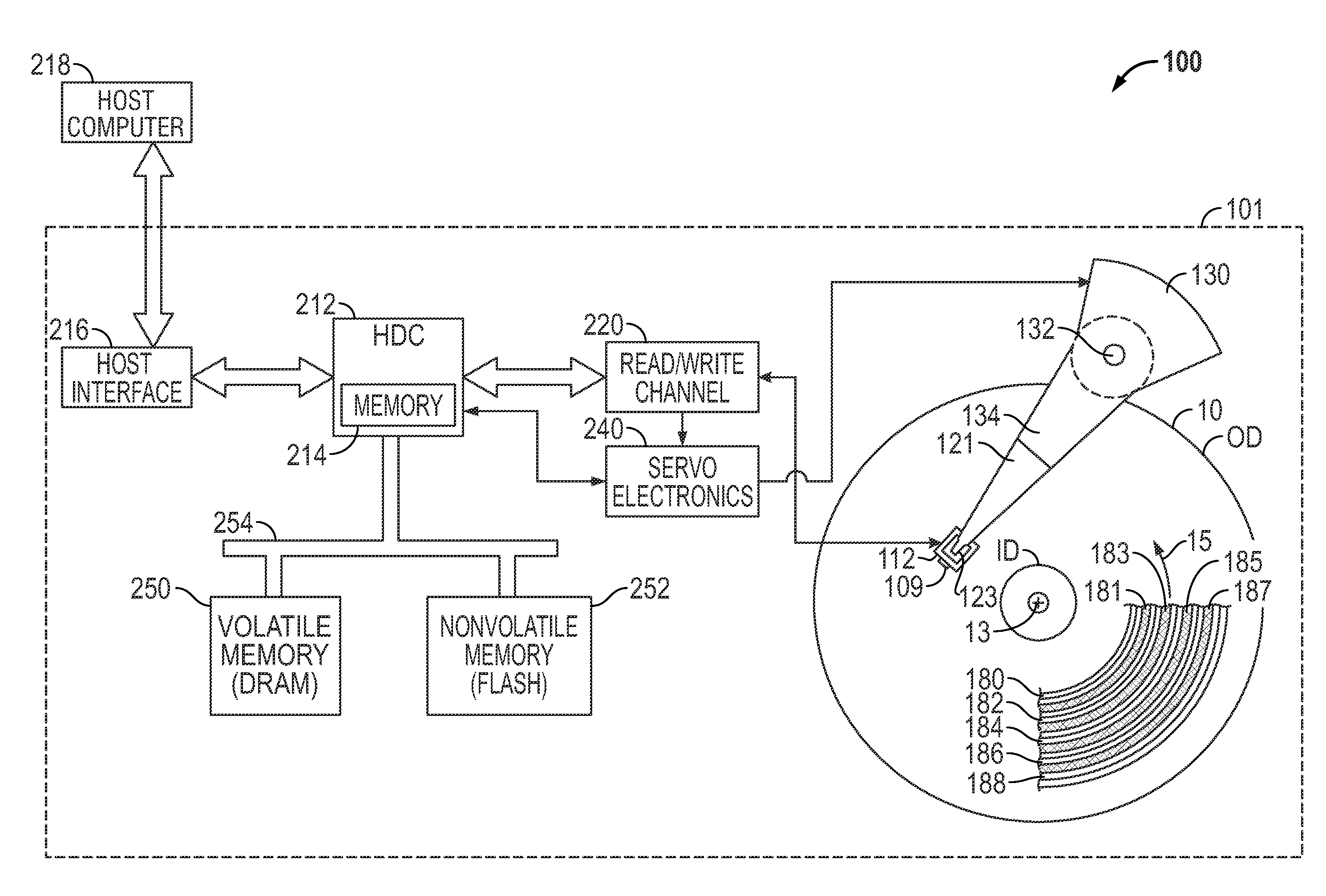
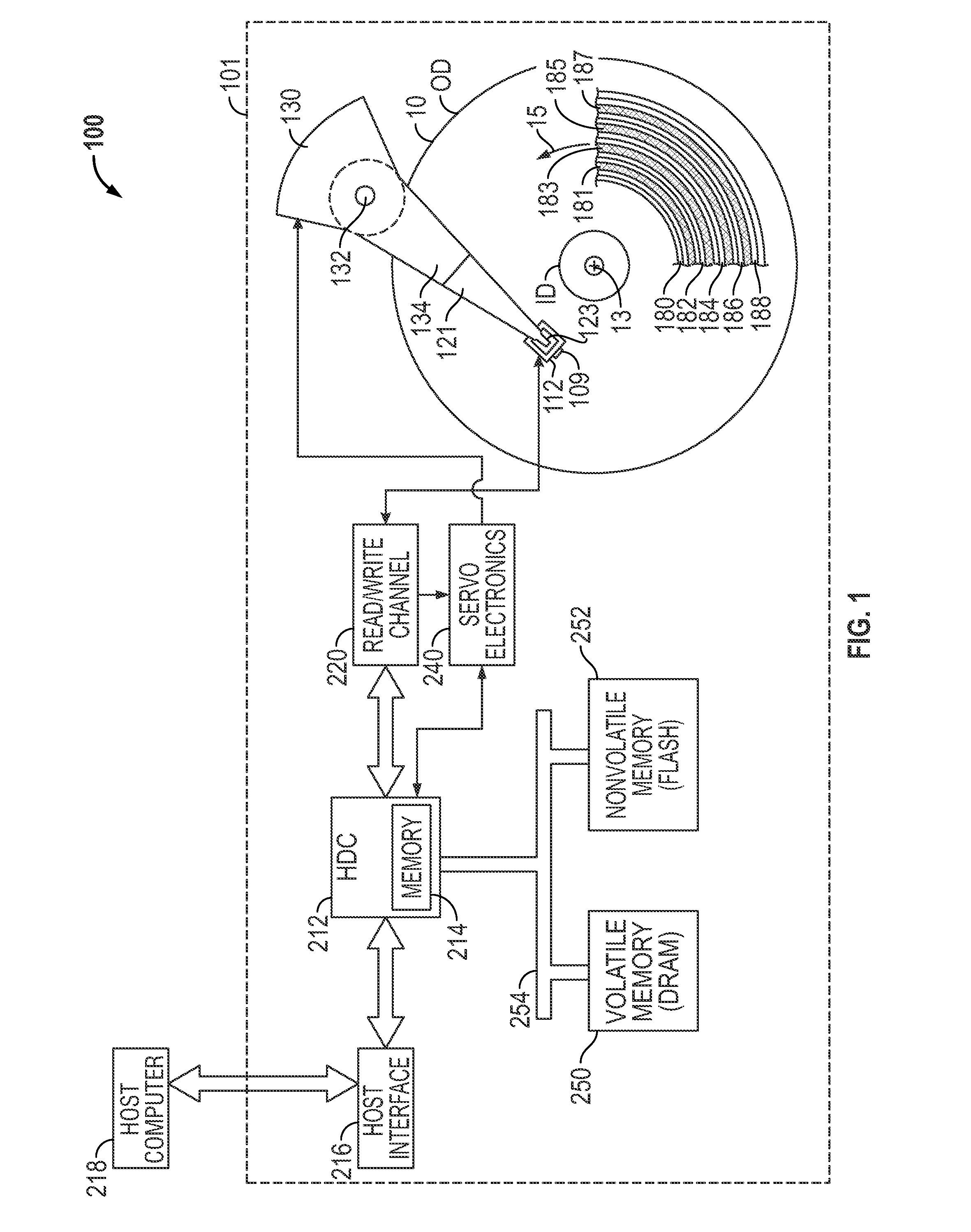
[0020]FIG. 1 is a top view of a disk drive 100 with shingled recording according to the invention. The disk drive has a housing or base 101 that supports an actuator 130 and a spindle motor (not shown) for rotating the magnetic recording disk 10 about its center 13 in the direction indicated by arrow 15. The actuator 130 may be a voice coil motor (VCM) rotary actuator that has a rigid arm 134 and rotates about pivot 132. A head-suspension assembly includes a suspension 121 that has one end attached to the end of actuator arm 134, a flexure 123 attached to the other end of suspension 121, and a head carrier, such as an air-bearing slider 122, attached to the flexure 123. The suspension 121 permits the slider 122 to be maintained very close to the surface of disk 10 and the flexure 123 enables the slider 122 to “pitch” and “roll” on an air-bearing generated by the rotating disk 10. The slider 122 supports the read / write or recording head 109 located on the end face 112 of slider 122. ...


PUM


Abstract

A shingled magnetic recording hard disk drive that uses writeable cache tracks in the inter-band gaps between the annular data bands minimizes the effect of far track erasure (FTE) in the boundary regions of annular data bands caused by writing to the cache tracks. Based on the relative FTE effect for all the tracks in a range of tracks of the cache track being written, a count increment (CI) table or a cumulative count increment (CCI) table is maintained. For every writing to a cache track, a count for each track in an adjacent boundary region, or a cumulative count for each adjacent boundary region, is increased. When the count value for a track, or the cumulative count for a boundary region, reaches a predetermined threshold the data is read from that band and rewritten to the same band.

Description

RELATED APPLICATION[0001]This application is related to application Ser. No. ______ filed ______, 2012 concurrently with this application and titled “SHINGLED MAGNETIC RECORDING DISK DRIVE WITH MINIMIZATION OF THE EFFECT OF FAR TRACK ERASURE ON ADJACENT DATA BANDS” (Attorney Docket No. HSJ920110116US1).BACKGROUND OF THE INVENTION[0002]1. Field of the Invention[0003]This invention relates generally to magnetic recording hard disk drives (HDDs), and more particularly to a shingled magnetic recording (SMR) HDD that minimizes the effect of far track erasure (FTE) on data tracks in the boundary regions of data bands.[0004]2. Description of the Related Art[0005]Magnetic recording disk drives that use “shingle writing”, also called “shingled recording” or “shingled magnetic recording” (SMR), have been proposed, for example as described in U.S. Pat. No. 6,185,063 B1 and U.S. Pat. No. 6,967,810 B2. In SMR, the write head, which is wider than the read head in the cross-track direction, writes...

Claims


Application Information

Patent Timeline
IPC IPC(8): G06F12/08
CPCG11B5/012G06F12/0866G11B20/1879G11B20/10388G11B20/10527G06F2212/313
Inventor BANDIC, ZVONIMIR Z.GUYOT, CYRILHARAYAMA, TOMOHIROMATEESCU, ROBERT EUGINIUTHORSTENSON, SHAD HENRYTSAI, TIMOTHY KOHCHIH
Owner WESTERN DIGITAL TECH INC
Learn More