Methods and Systems for Restraining a Flow Line

Inactive Publication Date: 2013-09-26
S P M FLOW CONTROL
View PDF5 Cites 12 Cited by
  • Summary
  • Abstract
  • Description
  • Claims
  • Application Information

AI Technical Summary

Benefits of technology

[0027]Certain embodiments provide safety restraint systems for restraining the movement of a high pressure flow line and/or a well service flow line in the event of rupture and/or substantial disruption of the flow line. The systems disclosed herein may be used on one or more of the following: a portion of the flow line, a substantial portion of the flow line and the entire flow line. The flow line including at least one swivel assembly secured between first and second pipes of the flow line by first and second couplings, respectively, the swivel having portions that are movable from an in-line position relative to the first and second pipes to a plurality of angled positions relative to the first and second pipes, including at least one restraining link between the first and second pipes including a

Problems solved by technology

The high pressure fluids create cracks or fissures in the formation, causing the oil or gas to flow more freely from the formation.
Even though the flow lines are designed to withstand high pressures, ruptures in the tubular components and couplings may still occur.

Method used


Image

  • Methods and Systems for Restraining a Flow Line
  • Methods and Systems for Restraining a Flow Line
  • Methods and Systems for Restraining a Flow Line

Examples


Example

Example 1

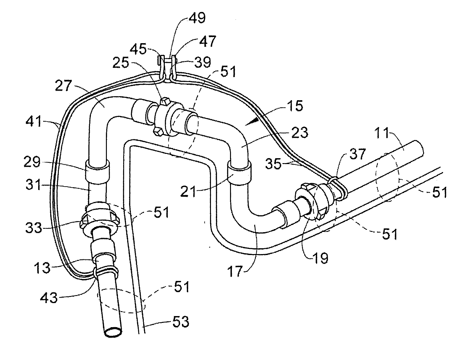
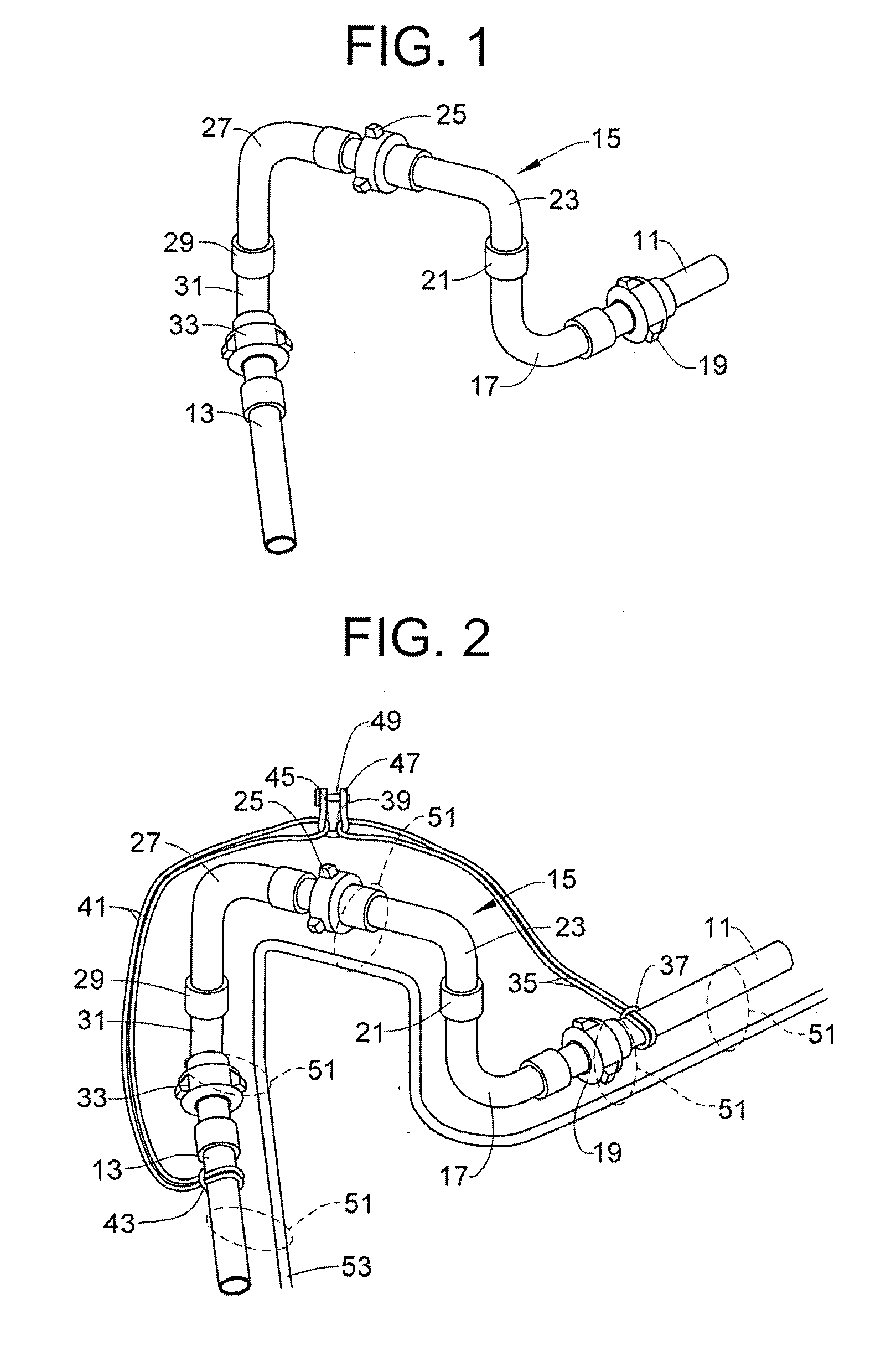
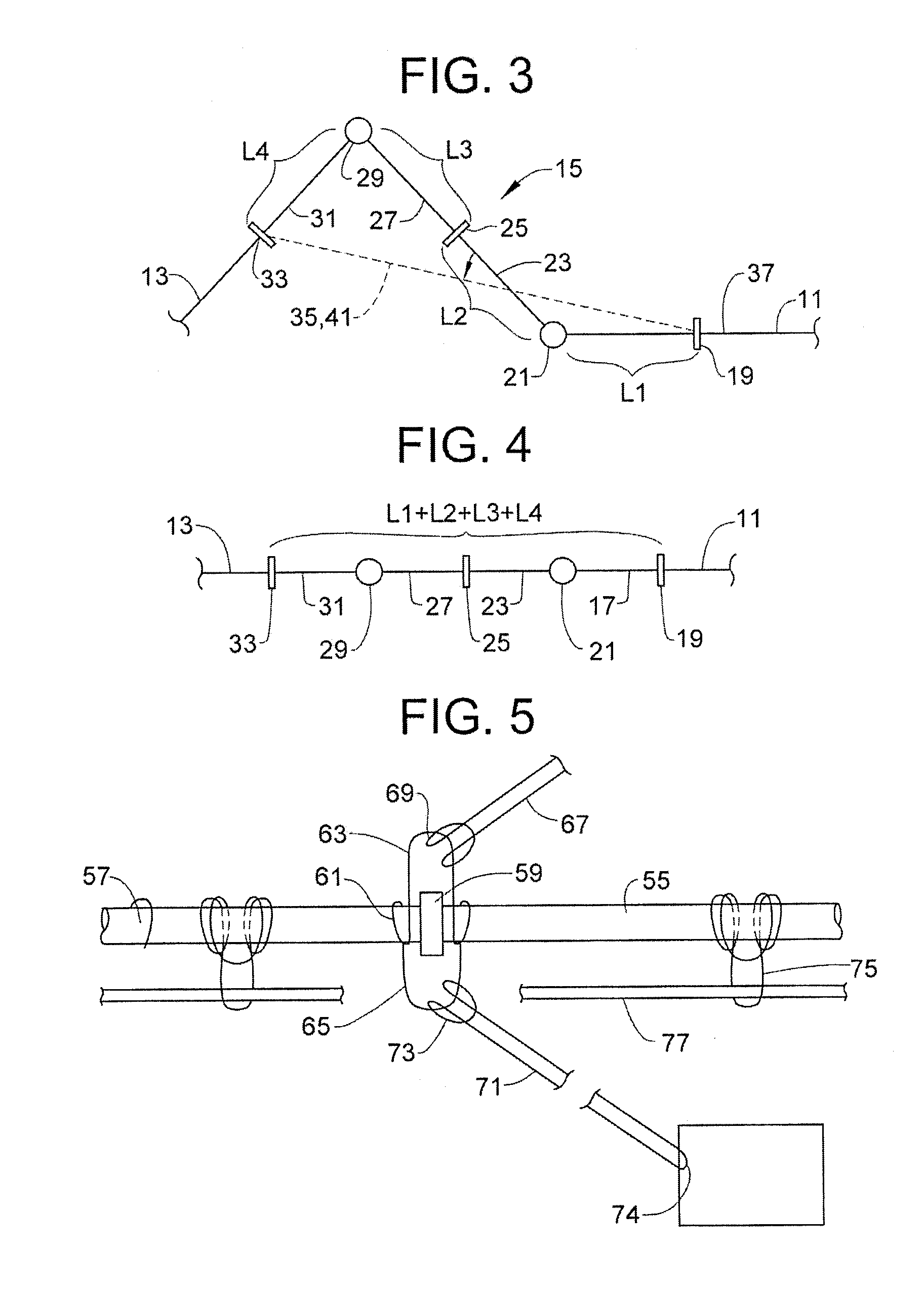
[0068]A method of substantially restraining movement of at least a portion of a high pressure flow line in the event of a rupture and / or substantial dislocation of at least a portion of the flow line, the flow line including at least one swivel assembly secured between first and second pipes of the flow line by first and second couplings, respectively, the at least one swivel assembly having portions that are movable from an in-line position relative to the first and second pipes to a plurality of angled positions relative to the first and second pipes, the method comprising: securing opposite ends of at least one restraining link between the first and second pipes, creating a first fixed end of the at least one restraining link at the first pipe that is substantially immoveable toward the second pipe and creating a second fixed end of the at least one restraining link at the second pipe that is substantially immoveable toward the first pipe; wherein a length of the at leas...

Example

Example 2

[0069]The method according to example 1, wherein the at least one restraining link comprises first and second flexible loops, and the method further comprises: looping a portion of the first loop around the first pipe to create the first fixed end; looping a portion of the second loop around the second pipe to create the second fixed end; and securing free end portions of the first and second loop to each other with a fastener and / or to another securing site.

Example

Example 3

[0070]The method according to one or more examples, wherein: the at least one restraining link comprises a single loop; and the second fixed end is formed by looping a portion of the single loop around the second pipe and securing the portion to the second pipe with the fastener.


PUM


Abstract

Loops may be installed on a high pressure flow line and/or well service flow line to reduce movement of components of the flow line in the event of a rupture and/or substantial dislocation of at least a portion of the flow line. At least one restraining link having at least one flexible loop extends across at least one swivel assembly and is secured to adjoining pipes of the flow line. The at least one restraining link is secured while the swivel assembly is in an angled position. A length of the at least one restraining link is less than a horizontal length of the at least one swivel assembly while in an in-line position, preventing, or substantially preventing, the swivel assembly from moving to, or substantially towards, the in-line position. Also, at least one flexible anchor support tether may be wrapped around a coupling between tubular components of the flow line so as to create a right connection loop and a left connection loop. Right and left anchor tethers are looped through the connection loops. Opposite end portions of the anchor tethers are connected to well site equipment and/or other suitable securing sites.

Description

CROSS-REFERENCE TO RELATED APPLICATIONS[0001]This application claims priority to U.S. Provisional Application No. 61 / 613,849 (Internal Docket HP70-076), entitled, “Method and System For Restraining A Flow Line” filed on Mar. 21, 2012. This U.S. provisional application is incorporated herein by reference in its entirety. In addition, U.S. Pat. No. 6,481,457, in its entirety, is incorporated herein by reference.TECHNICAL FIELD[0002]This disclosure relates in general to safety lines attached to flow lines employed in well service operations or other types of applications where safety or restraint lines may be employed. Certain embodiments are directed to methods and / or systems where there is a need to eliminate a need for, or reduce the need for, tubular crossover anchors.BACKGROUND OF THE DISCLOSURE[0003]In oil and gas wells, it is often necessary to stimulate the well in order to increase its production. One method is to fracture the producing formation by introducing fluids into the...

Claims


Application Information

Patent Timeline
IPC IPC(8): F16L55/00
CPCF16L55/005Y10T137/0441Y10T137/6851
Inventor MONEY, JACOB A.MOORE, ROBERT GARY
Owner S P M FLOW CONTROL
Why Eureka
Try Eureka