Battery pack mounting structure for electric car

a technology for mounting structures and batteries, applied in the direction of electric propulsion mounting, battery/fuel cell control arrangement, electric propulsion mounting, etc., can solve the problems of difficult to protect the battery pack sufficiently by the mount frame, and the risk of the battery pack moving toward the vehicle front side, etc., to achieve the effect of suppressing the deformation of the rear side members

Active Publication Date: 2013-09-26
SUZUKI MOTOR CORP
View PDF19 Cites 29 Cited by
  • Summary
  • Abstract
  • Description
  • Claims
  • Application Information

AI Technical Summary

Benefits of technology

[0013]Since the front side portion of the support frame is coupled to the cross member by the coupling portion, the sub-frame transmits a forward force acting on the support frame to the cross member arranged at a position below the bent portions that connect the rising portions and the rear portions of the rear side members, and can thereby suppress deformation of the rear side members at the bent portions when an impact force is applied from the vehicle rear side.
[0014]Also, in the sub-frame, since the both vehicle-widthwise side portions of the support frame are coupled to the rear portions of the rear side members by the coupling portions, the rear side members can be reinforced

Problems solved by technology

Thus, in the battery pack mounting structure according to the above publication, the battery pack is difficult to sufficiently protect by the mount frame.
Accordingly, in the battery pack

Method used


Image

  • Battery pack mounting structure for electric car
  • Battery pack mounting structure for electric car
  • Battery pack mounting structure for electric car

Examples


Embodiment Construction

[0022]In the following, an embodiment of the present invention will be described based on the drawings.

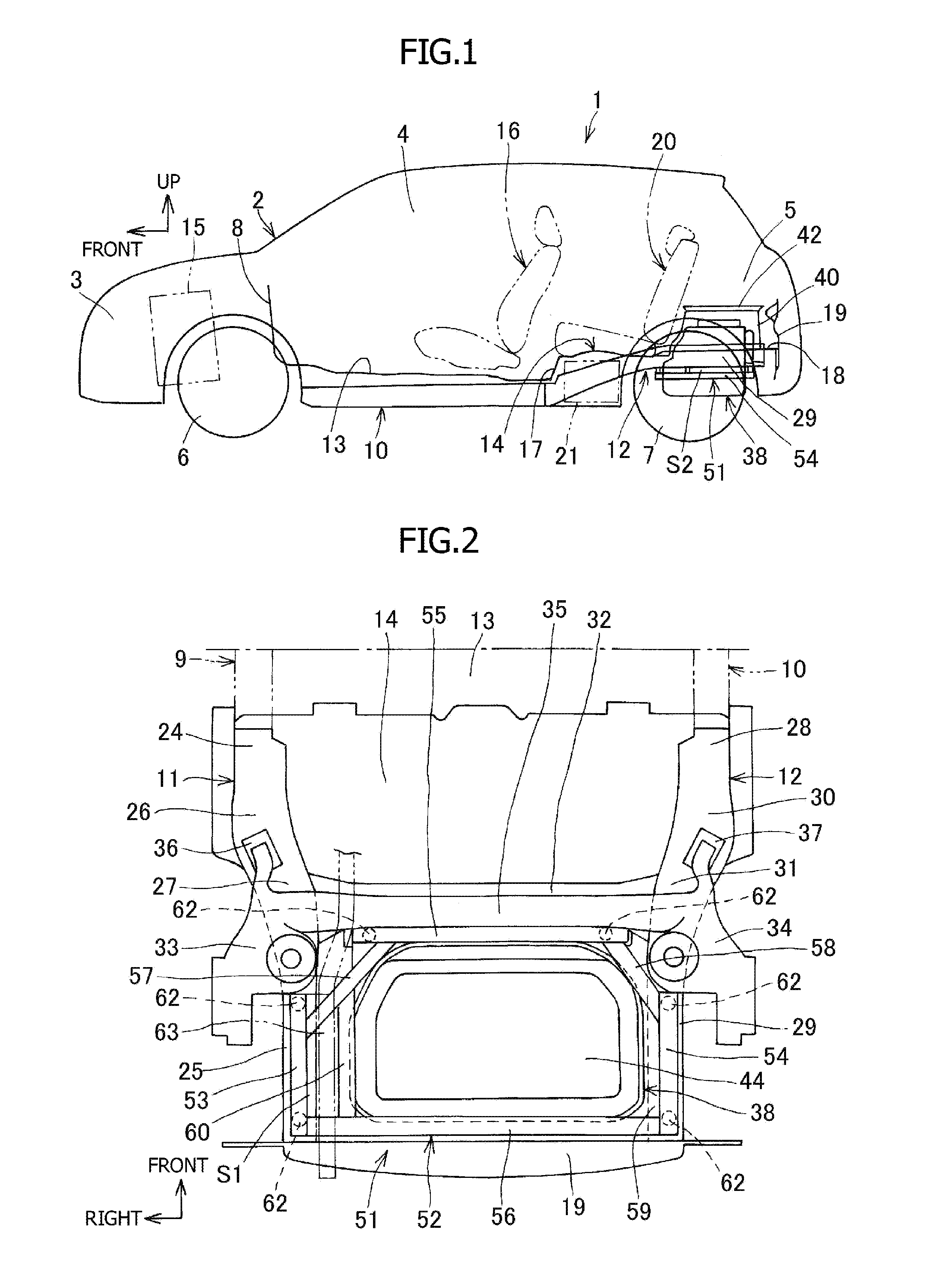
[0023]FIGS. 1 to 5 show the embodiment of the present invention. In FIG. 1, reference numeral 1 denotes an electric car, 2 a vehicle body, 3 an engine compartment, 4 a vehicle interior, 5 a trunk, 6 a front wheel, and 7 a rear wheel. In the electric car 1, a dash panel 8 that extends in a vehicle width direction is arranged at a front portion of the vehicle body 2. In the electric car 1, a pair of front side members 9 and 10 that extend in a vehicle longitudinal direction are arranged at both widthwise side portions of a center portion of the vehicle body 2, and a pair of rear side members 11 and 12 that extend in the vehicle longitudinal direction are arranged at both widthwise side portions of a rear portion of the vehicle body 2 as shown in FIG. 2.

[0024]The engine compartment 3 is formed on the front side of the dash panel 8 at the front portion of the vehicle body 2. A front fl...


PUM


Abstract

An object of the present invention is to protect a battery pack in the event of a vehicle rear impact in an electric car in which the battery pack is arranged between rear side members arranged at a vehicle rear portion.
The present invention provides a battery pack mounting structure for electric cars in which a pair of rear side members having a front portion, a rear portion, and a rising portion are arranged at both vehicle-widthwise side portions, intermediate portions of the respective rear side members are coupled to each other by a cross member, and a battery pack is mounted on a vehicle body by a sub-frame that is coupled to the respective rear side members and the cross member, wherein the cross member is arranged at a position below a bent portion that connects the rising portion and the rear portion of each of the rear side members, the sub-frame includes a ring-like support frame that extends in a horizontal direction and surrounds an outer periphery of the battery pack, and a front side portion and both vehicle-widthwise side portions of the support frame are respectively coupled to the cross member and the rear portions of the respective rear side members by coupling portions.

Description

CROSS-REFERENCE TO RELATED APPLICATIONS[0001]The present application claims priority to Japanese Patent Application No. 2012-068587 filed Mar. 26, 2012, the content of which is incorporated by reference herein its entirety.BACKGROUND OF THE INVENTION[0002]1. Field of the Invention[0003]The present invention relates to a battery pack mounting structure for electric cars, and more particularly, relates to a battery pack mounting structure for electric cars for use to protect a battery pack mounted on an electric car which runs by a motor driving force from an impact force in the event of a rear impact.[0004]2. Description of Related Art[0005]Electric cars which run by a motor driving force need to have a larger battery capacity so as to run longer distances. At this point, when the battery capacity increases, a larger and heavier battery pack is required to store a battery. Thus, the battery pack is often mounted in a lower portion of a vehicle or a rear portion of the vehicle.[0006]A...

Claims


Application Information

Patent Timeline
IPC IPC(8): B60K1/04
CPCB60K2001/0416B60K1/04B60K2001/0438B60L58/21B60L50/66B60L50/64Y02T10/70
Inventor NITAWAKI, KUNIHIRO
Owner SUZUKI MOTOR CORP
Why Eureka
Try Eureka