

Gas turbine start with frequency convertor
a technology of frequency converter and gas turbine, which is applied in the direction of engine starter, turbine/propulsion engine ignition, electric generator control, etc., can solve the problems of waste gas temperature of turbine, unnecessary transients of hot gas, and relatively time-consuming process, so as to reduce the thermal load of turbin
- Summary
- Abstract
- Description
- Claims
- Application Information
AI Technical Summary
Benefits of technology
Problems solved by technology
Method used
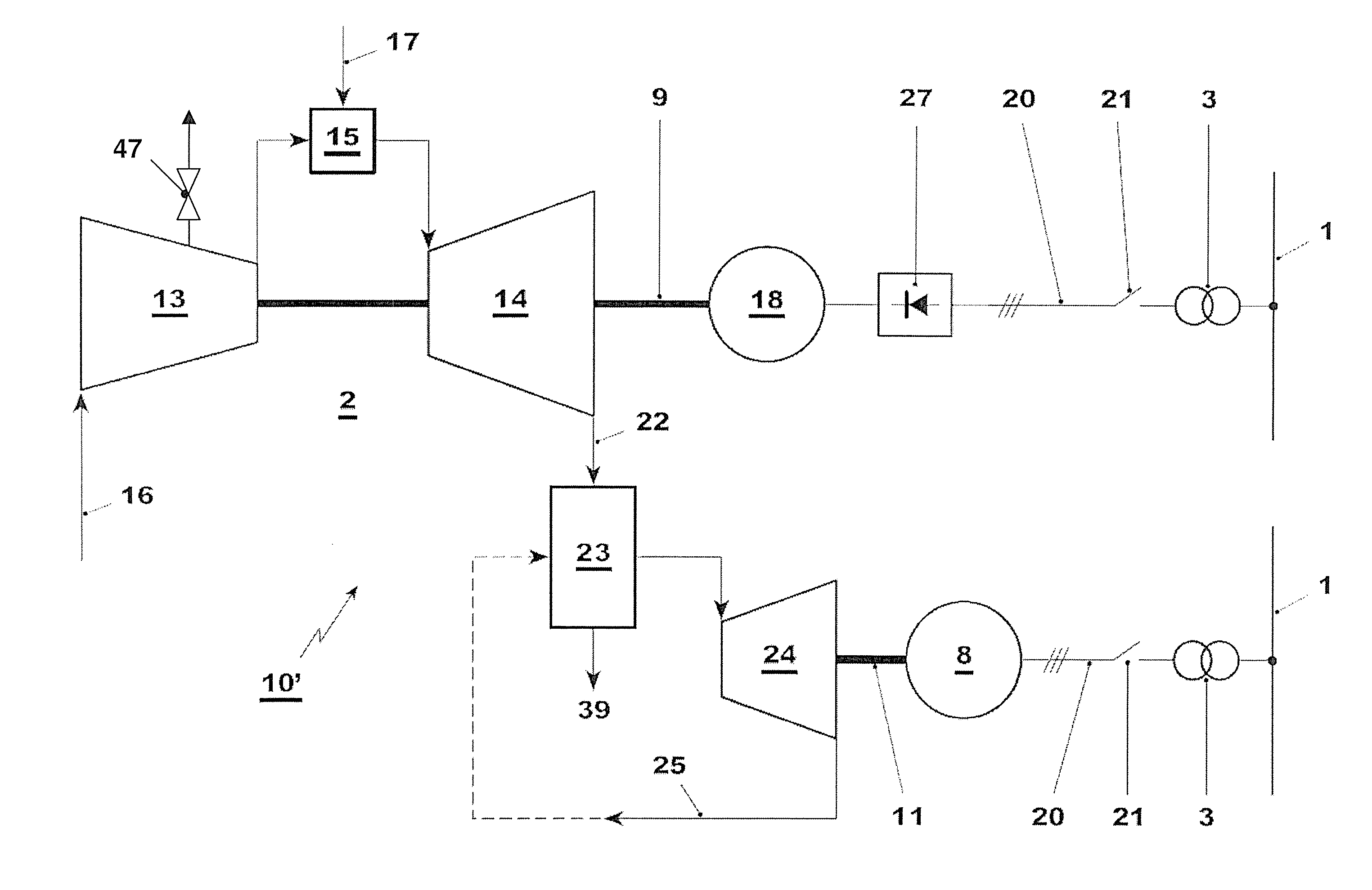
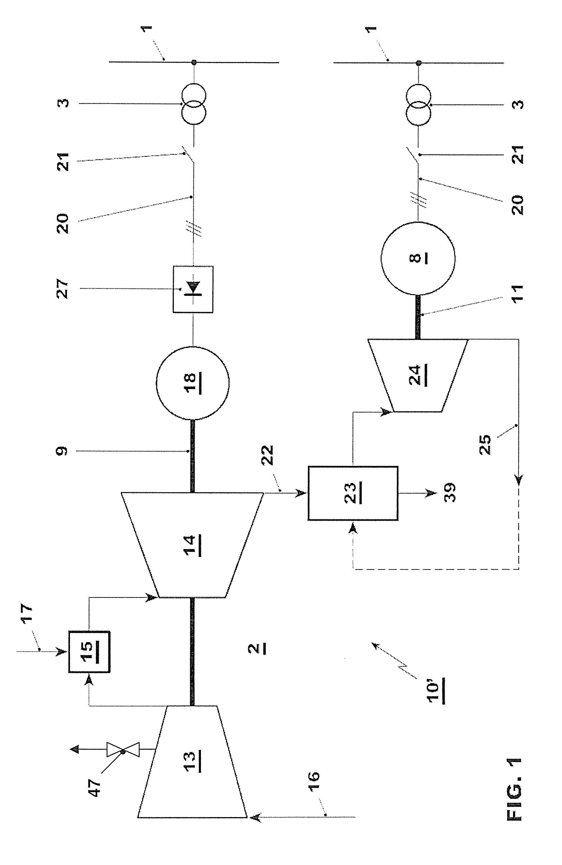
Image

Examples
first embodiment
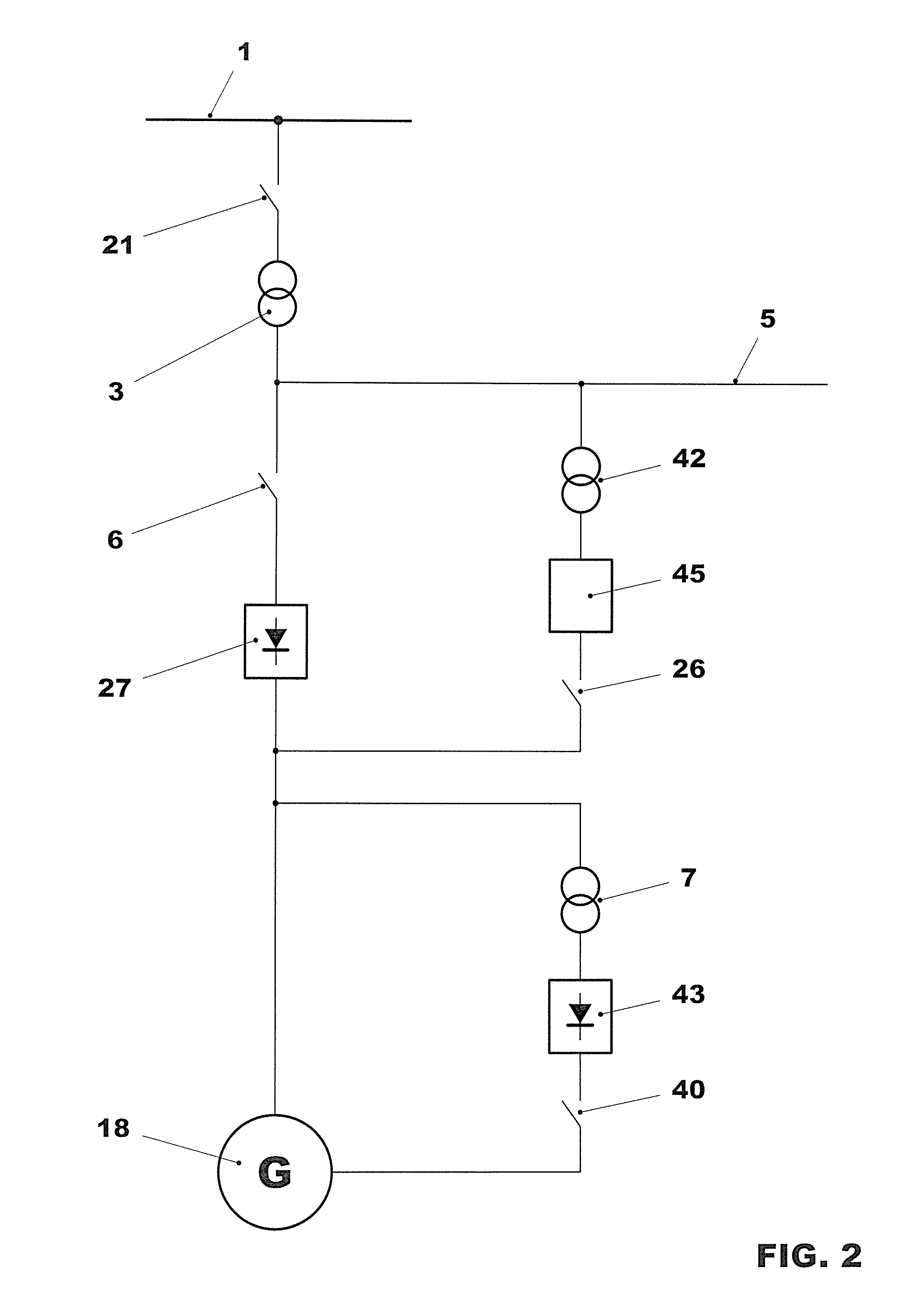
[0039]A highly simplified detail from a single line diagram of the power plant according to the invention is illustrated in FIG. 2. This allows a feed of electrical power into the grid 1 before the gas turbine has reached the nominal rotational speed. It shows a conventional generator 18 driven by at least one turbine, the output power of said generator being transferred via a power plant grid 5. The power plant grid 5 contains high-voltage lines and a generator circuit breaker 6 with which the generator 18 can be separated from the power plant grid 5. The current generated by the generator 18 is fed into the grid 1 via a grid connection 20, a step-up transformer 3 and a grid high-voltage switch 21. The power grid that belongs to the power plant and consists of a medium-voltage grid and a low-voltage grid supplied thereby is typically supplied from the power plant grid 5 via an auxiliary transformer and a high-voltage switch (not shown).
[0040]The generator excitation current is draw...
second embodiment
[0043]the power plant according to the invention is illustrated in FIG. 3. The exemplary embodiment shown in FIG. 3 is based on that of FIG. 2. In this embodiment, a static start-up device 45 for the start of the gas turbine 2 has been omitted however. For the start, the frequency convertor 27 is used to control the generator 18 as a motor. To this end, the frequency convertor 27 in this embodiment is supplied with current from the grid 1 directly by the step-up transformer 3 during motor operation of the generator 18.
[0044]A further embodiment of the power plant according to the invention is illustrated in FIG. 4. Depending on the design of the frequency convertor 27 and voltage before the step-up transformer 3, the frequency convertor 27 cannot be used directly to control the generator 18 as a motor. In order to supply the frequency convertor 27 with current at a lower voltage level for the start, a start-up transformer 42 (also called a starting transformer) and a start-up switch...
PUM
 Abstract
Description
Claims
Application Information