Synchronous machine control apparatus

a technology of control apparatus and synchronous machine, which is applied in the direction of dynamo-electric converter control, motor/generator/converter stopper, dynamo-electric gear control, etc., can solve the problem of a large obstacle factor to mounting the temperature detection devi

Inactive Publication Date: 2013-09-26
MITSUBISHI ELECTRIC CORP
View PDF3 Cites 37 Cited by
  • Summary
  • Abstract
  • Description
  • Claims
  • Application Information

AI Technical Summary

Benefits of technology

[0024]The synchronous machine control apparatus according to the present invention makes it possible to drive a synchronous machine while estimating with less map data a high-accuracy permanent-magn...

Problems solved by technology

However, due to a space problem caused by the structure of the synchronous machine, a case protecting the outside of the synchronous machine, or the like, it is difficult to directly mount a temperature detection device on the permanent magnet; furthermore, most of synch...

Method used


Image

  • Synchronous machine control apparatus
  • Synchronous machine control apparatus
  • Synchronous machine control apparatus

Examples


embodiment 1

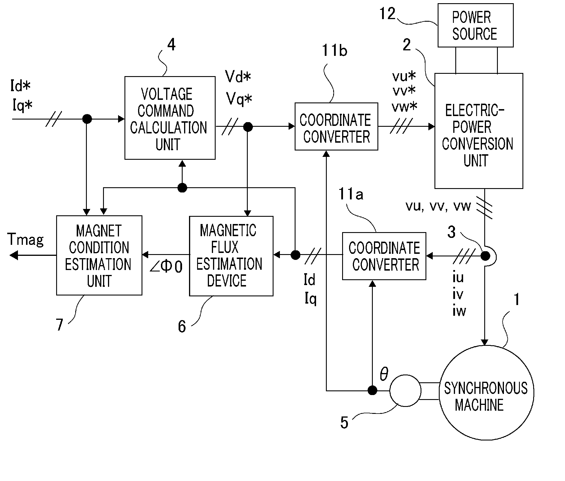
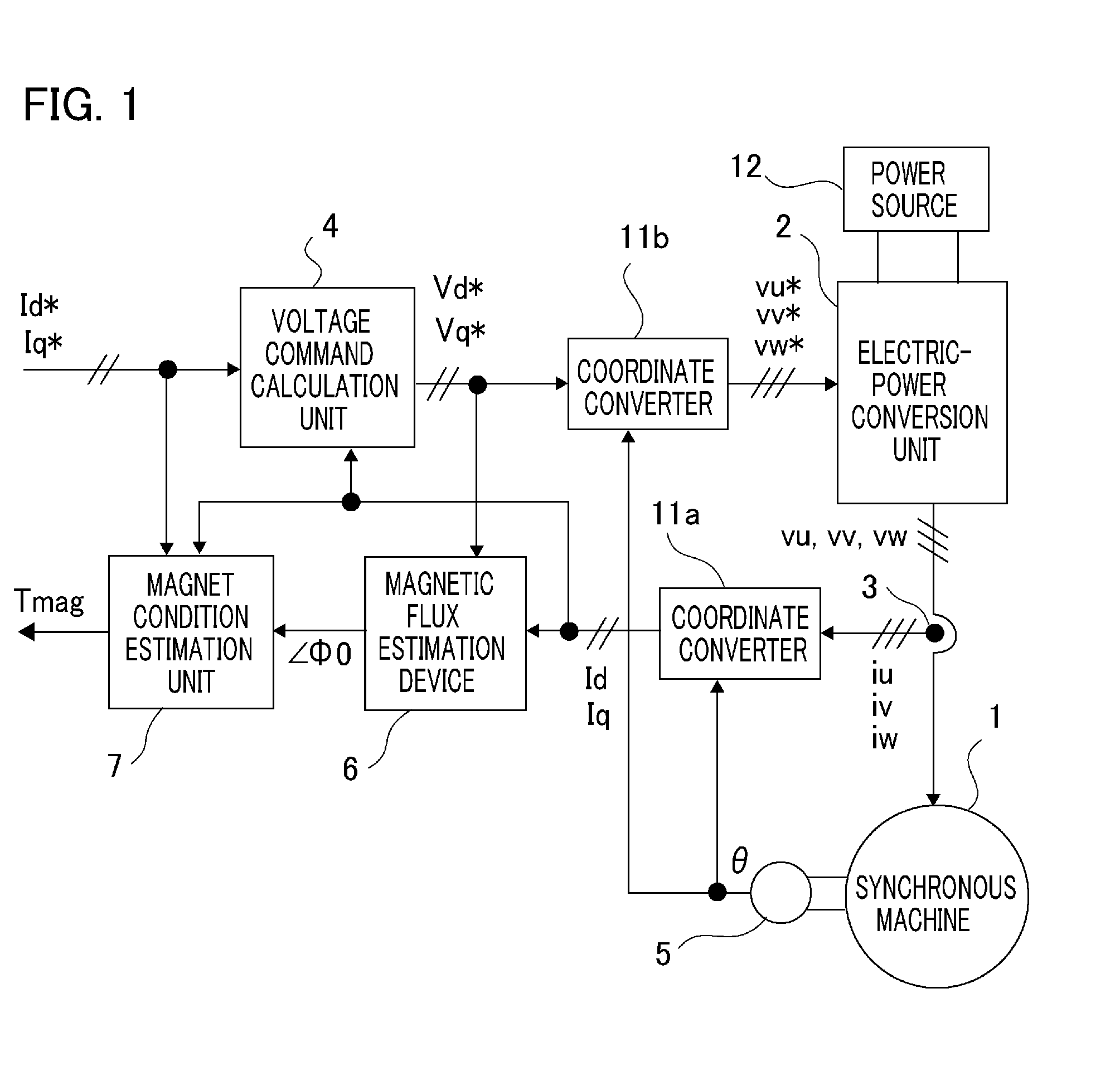
[0050]Hereinafter, there will be explained the configuration of a synchronous machine control apparatus according to Embodiment 1 of the present invention and the functions of constituent elements. FIG. 1 is a system configuration diagram illustrating a synchronous machine control apparatus according to Embodiment 1 of the present invention, along with a synchronous machine. A synchronous machine 1 according to the present invention has a magnetic-field permanent magnet.

[0051]At first, with regard to the configuration, of a synchronous machine control apparatus according to Embodiment 1 of the present invention, that is required for driving a synchronous machine, there will be explained the flow from the output side of an electric-power conversion unit to the input side thereof where a voltage command is created. In FIG. 1, the synchronous machine 1 having a magnetic-field permanent magnet is controlled by a synchronous machine control apparatus according to Embodiment 1 of the pres...

embodiment 2

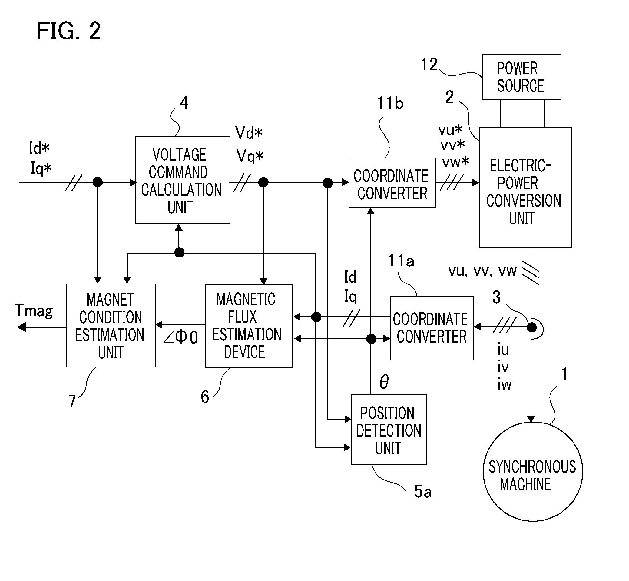
[0086]Next, there will be explained a synchronous machine control apparatus according to Embodiment 2 of the present invention. FIG. 7 is a system configuration diagram illustrating a synchronous machine control apparatus according to Embodiment 2 of the present invention, along with a synchronous machine. In Embodiment 1, as the control commands, the d-q axis current commands Id* and Iq* are given; however, in Embodiment 2, as the control commands, the total armature-interlinked magnetic flux command Φ* and the δ-axis current command Iδ* are given. Although not illustrated in particular, there may be adopted, also in Embodiment 2, a configuration in which as illustrated in FIG. 2, there is provided the position detection unit 5 that obtains the rotor position θ through an estimation calculation.

[0087]Hereinafter, the parts different from those in Embodiment 1 will be mainly explained; the explanation for the same parts as those in Embodiment 1 will appropriately be omitted. At firs...

embodiment 3

[0108]Next, there will be explained a synchronous machine control apparatus according to Embodiment 3 of the present invention. FIG. 12 is a system configuration diagram illustrating a synchronous machine control apparatus according to Embodiment 3 of the present invention, along with a synchronous machine; FIG. 13 is a system configuration diagram illustrating a variant example of synchronous machine control apparatus according to Embodiment 3 of the present invention, along with a synchronous machine. As illustrated in each of FIGS. 12 and 13, in a synchronous machine control apparatus according to Embodiment 3 of the present invention, there is added a control command calculation unit 8 (or 8a), which is a higher-hierarchy command creation system for creating the control commands based on the torque command so that the torque command is limited in accordance with the γ-axis current Iγ and the control commands are outputted in accordance with the limited torque command.

[0109]In FI...


PUM


Abstract

A synchronous machine control apparatus is characterized by including a magnet condition estimation unit (7, 7a) that estimates the temperature or the magnetic flux of a permanent magnet that forms the magnetic field of a synchronous machine (1), and is characterized in that the magnet condition estimation unit (7, 7a) coordinate-converts an armature current into currents on the γ-δ axis consisting of the γ axis and the δ axis that is perpendicular to the γ axis, based on the rotor position and the estimated γ axis, and estimates the temperature or the magnetic flux of the permanent magnet, based on the control command for the synchronous machine (1) and the γ-δ axis currents.

Description

BACKGROUND OF THE INVENTION[0001]1. Field of the Invention[0002]The present invention relates to a synchronous machine control apparatus provided with an electric-power conversion unit that drives a synchronous machine.[0003]2. Description of the Related Art[0004]As is well known, in the case where a synchronous machine having a permanent magnet, as a magnet-field magnet, is controlled by a synchronous machine control apparatus having an electric-power conversion unit such as an inverter, a temperature rise due to energization of the armature of a synchronous machine or the like causes a so-called “demagnetization” phenomenon in which the intensity of magnetization of the magnetic-field permanent magnet, i.e., the magnetic flux is reduced; furthermore, when the allowable temperature is exceeded, a so-called “irreversible demagnetization” phenomenon is caused in which even when the temperature falls down to the normal temperature, the magnetic flux does not return to the state at a t...

Claims


Application Information

Patent Timeline
IPC IPC(8): H02P21/14H02P27/04H02P21/00H02P21/18H02P21/22H02P21/24H02P21/28H02P23/12H02P23/14H02P27/08H02P29/00H02P29/62H02P29/64
CPCH02P21/141H02P29/0066H02P29/662
Inventor KOBAYASHI, TAKAHIKOANZAI, KIYOHARUWADA, NORIYUKIMATSUURA, DAIKI
Owner MITSUBISHI ELECTRIC CORP
Why Eureka
Try Eureka