Electrical discharge tube, illumination apparatus for display device, liquid crystal display device, and liquid crystal display television

a technology of illumination apparatus and discharge tube, which is applied in the direction of television system, process and machine control, instruments, etc., can solve the problems of easy deterioration of electrodes, shortening of life, and easy sputtering of emitter particles at too low temperatur

Inactive Publication Date: 2011-02-08
SHARP KK
View PDF10 Cites 0 Cited by
  • Summary
  • Abstract
  • Description
  • Claims
  • Application Information

AI Technical Summary

Benefits of technology

[0008]In order to overcome the problems described above, preferred embodiments of the present invention accurately hold and control temperatures in the electrodes in the electrical discharge tube.
[0010]According to this construction, the temperatures in the electrodes of the discharge tube can be more accurately grasped, and the temperatures in the electrodes of the discharge tube can be more properly controlled.
[0011]It is preferable that the electrical discharge tube is a hot cathode tube. A hot cathode tube has characteristics such that higher brilliance is obtained with comparatively lower voltage. However, the hot cathode tube has a problem that the electrodes are easy to be deteriorated and has a shorter life. That is, the emitter on the surface of the electrodes of the hot cathode tube is easy to vaporize at too high of a temperature; and, on the other hand, sputtering away of the particles of the emitter easily occurs at too low of a temperature.
[0012]When the foregoing construction is used for such a hot cathode tube, the temperatures in the electrodes are easily controlled with higher accuracy. This makes easier to prevent the vaporization and / or sputtering away of the emitter.
[0013]Also, when the temperature sensor is constituted by a thermocouple in the electrical discharge tube, excellent temperature detection at the electrodes, which are put in a higher temperature state, is enabled.

Problems solved by technology

However, the hot cathode tube has a problem that the electrodes are easy to be deteriorated and has a shorter life.
That is, the emitter on the surface of the electrodes of the hot cathode tube is easy to vaporize at too high of a temperature; and, on the other hand, sputtering away of the particles of the emitter easily occurs at too low of a temperature.

Method used


Image

  • Electrical discharge tube, illumination apparatus for display device, liquid crystal display device, and liquid crystal display television
  • Electrical discharge tube, illumination apparatus for display device, liquid crystal display device, and liquid crystal display television
  • Electrical discharge tube, illumination apparatus for display device, liquid crystal display device, and liquid crystal display television

Examples


first preferred embodiment

[0023]A first preferred embodiment of the present invention will be explained with reference to drawings.

General Construction

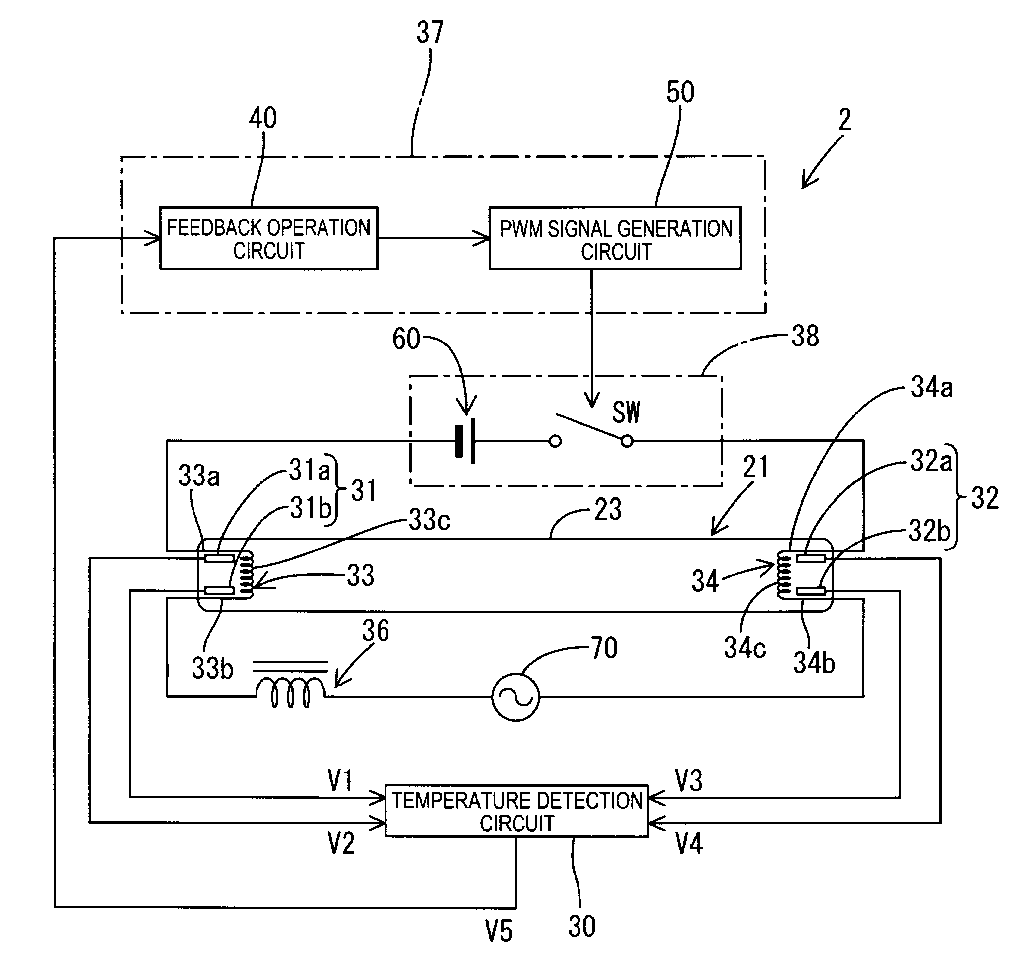
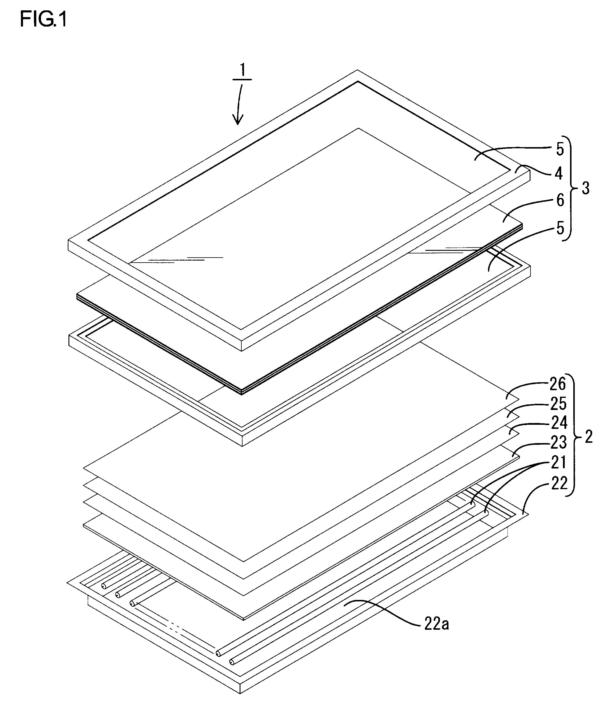
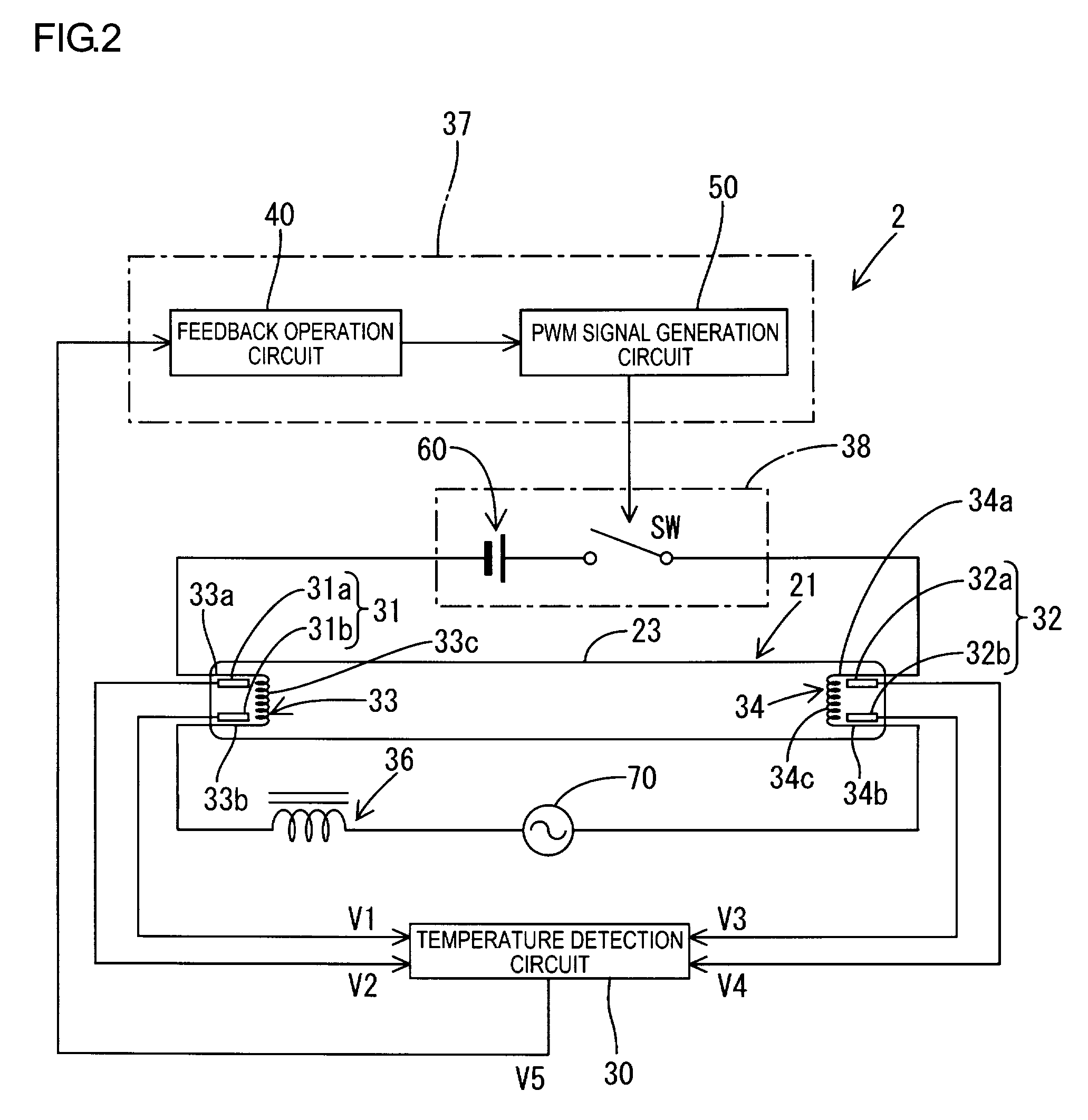
[0024]A liquid crystal display 1 in accordance with the present preferred embodiment corresponds to a display device of the present invention. The liquid crystal display 1 includes a backlight device 2 (the backlight device 2 corresponds to an illumination apparatus for a display device) and a display panel 3. The display panel 3 (the display panel 3 corresponds to a liquid crystal panel) is disposed in front of the backlight device and can display images. The backlight device 2, though it is not limited to this, is a so-called direct backlight device that includes a tray 22 that accommodates a plurality of hot cathode fluorescent tubes 21, a light guide plate 23 made of synthetic resin and disposed immediately above the tray 22, a diffuser sheet 24 disposed on the light guide plate 23, and two lens sheets 25, 26 disposed on the diffuser sheet 24. As illustrat...

second preferred embodiment

[0069]A second preferred embodiment of the present invention will be now explained with reference to FIG. 7.

[0070]The present preferred embodiment is different from the first preferred embodiment in the point that the configuration of the control section 37 is modified from the one illustrated in FIG. 2. Other configurations preferably are similar to the first preferred embodiment, and therefore, constructions similar to the first preferred embodiment are designated by the same numerals, while detailed explanations are omitted.

[0071]In the present preferred embodiment, the control section 37 is constituted by a discrimination circuit 55. The discrimination circuit 55 is a circuit that discriminates whether or not the temperature indicated by the value outputted from the temperature detection circuit 30 is within a predetermined temperature range. Specifically, a first threshold value corresponding to a lower limit temperature of a target temperature range and a second threshold valu...

third preferred embodiment

[0072]A third preferred embodiment of the present invention will be now explained with reference to FIG. 8.

[0073]The present preferred embodiment is different from the first preferred embodiment in the point that the control section 37 and the electrode heating circuit 38 are modified from the ones illustrated in FIG. 2. Other constructions are similar to the first preferred embodiment, and therefore, constructions similar to the first preferred embodiment are designated by the same numerals, while detailed explanations are omitted.

[0074]The present preferred embodiment is configured to control a resistance value of a variable resistor R1 based on the average temperature of the temperatures detected by the temperature sensors 31, 32, thereby controlling the amount to be supplied to the electrodes 33, 34. Specifically, similar to the first preferred embodiment, the feedback operation circuit 40 computes the control amount, and a driving circuit 80 controls the variable resistor 38 so...


PUM

PropertyMeasurementUnit
temperatureaaaaaaaaaa
frequenciesaaaaaaaaaa

Abstract

A backlight device includes a hot cathode fluorescent tube having a pair of electrodes, a power source arranged to apply voltage having an alternating component to at least one of the pair of electrodes, and an electrode heating circuit arranged to supply heating current to the electrodes. The backlight device further includes temperature sensors that detect the temperatures in the electrodes to be supplied with the heating current. Based on the results detected by the temperature sensors, a switch element is driven by the control section. The heating current is thus controlled. With this, the temperatures in the electrodes of the electrical discharge tube can be more accurately grasped, and the temperatures in the electrodes of the discharge tube can be more properly controlled.

Description

BACKGROUND OF THE INVENTION[0001]1. Field of the Invention[0002]The present invention relates to an electrical discharge tube, an illumination apparatus for a display device, a liquid crystal display device, and a liquid crystal display television.[0003]2. Description of the Related Art[0004]A liquid crystal panel for use with a liquid crystal display device such as a liquid crystal display television does not emit light by itself, and therefore needs an illumination apparatus for the display device separately as an external lamp, which is a so-called a backlight device. The backlight device is installed on the backside or on the side of the liquid crystal panel, and generally includes a metal base, a plurality of electrical discharge tubes, and a plurality of optical elements. The metal base has an open face on the liquid crystal panel side. The electrical discharge tubes are accommodated as lamps in the base. The optical elements (a diffuser plate and the like) are disposed over t...

Claims


Application Information

Patent Timeline
Patent Type & Authority Patents(United States)
IPC IPC(8): H01J13/32H05B37/02G02F1/133G02F1/13357H01J61/067H01J61/30H01J61/56H05B41/24
CPCG02F1/133604H01J61/526H01J61/56H05B41/295G02F2001/133612G02F2201/58G02F1/133612
Inventor TAKATA, YOSHIKI
Owner SHARP KK
Why Eureka
Try Eureka