Apparatus, method, and system for independent aiming and cutoff steps in illuminating a target area

a target area and cutoff step technology, applied in the field of apparatus, method and system for independent aiming and cutoff steps in illuminating a target area, can solve the problems of reducing the uniformity of lighting, waste of light, and potential nuisance, and reducing the epa. , to achieve the effect of increasing glare control, reducing epa, and increasing lighting uniformity

Active Publication Date: 2013-09-26
MUSCO
View PDF12 Cites 71 Cited by
  • Summary
  • Abstract
  • Description
  • Claims
  • Application Information

AI Technical Summary

Benefits of technology

[0009]Envisioned is a compact lighting fixture designed to accommodate a plurality of adjustable light sources, and apparatus, systems, and methods for independent but cooperative light directing and light redirecting thereof such that a complex target area may be adequately illuminated with increased glare control, reduced EPA, and increased lighting uniformity as compared to at least most conventional floodlight-type fixtures for sports lighting applications.

Problems solved by technology

This light, commonly referred to as spill light, is wasteful and a potential nuisance (e.g., to spectators in bleachers 515) or hazardous (e.g., to drivers on a road adjacent to target area 5).
Further, replacing a single traditional light source with a plurality of compact and aimable light sources provides the potential to create complex beam patterns from a limited number of fixtures since the light output from each LED can be precisely and independently directed and redirected; if, of course, that potential can be logically and economically realized.
While a host of LED lighting fixtures have been designed for downlight applications (i.e., lighting applications that direct light generally downward towards the base of a pole to which the LEDs are affixed)—see, for example, U.S. Pat. Nos. 7,771,087 and 8,342,709—pivot those fixtures about their connection point to a pole so to project light outward and away from the pole (i.e., a floodlighting application such as that illustrated in FIGS. 1A-C) and a problem becomes apparent; namely, glare.
Because there is no external visor on LED fixtures such as the aforementioned, the LEDs are directly viewable and cause glare.
One might add an external visor such as in FIG. 1C so to reduce glare, but then there is the concern of undesirable lighting effects such as shadowing and uneven illumination because the LEDs contained therein are each aimed and paired with an optic so to produce a fixed aiming angle and beam pattern—and are not designed to cooperate with a single external visor.
An increased EPA may require a more substantial pole or more robust means of affixing the fixture to the pole so to address increased wind loading, which may add cost.
Thus, attempting to modify an existing LED downlight fixture to produce an LED floodlight fixture which is suitable for a sports lighting application may not be economically feasible.

Method used


Image

  • Apparatus, method, and system for independent aiming and cutoff steps in illuminating a target area
  • Apparatus, method, and system for independent aiming and cutoff steps in illuminating a target area
  • Apparatus, method, and system for independent aiming and cutoff steps in illuminating a target area

Examples


embodiment 1

[0031]B. Exemplary Method and Apparatus Embodiment 1

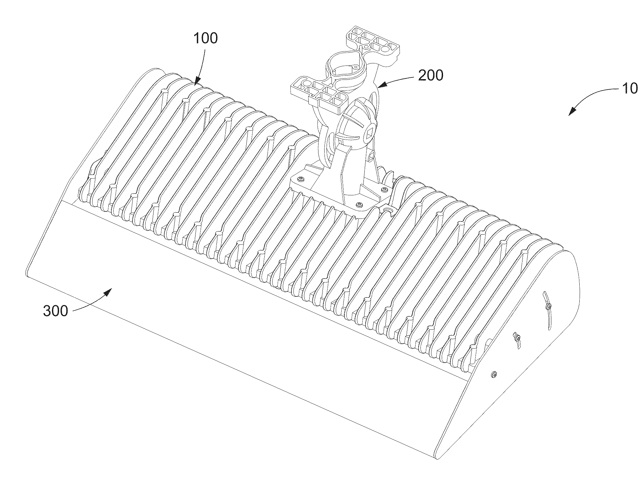
[0032]A more specific exemplary embodiment, utilizing aspects of the generalized example described above, will now be described. FIGS. 2A-H illustrate various views of a first envisioned lighting fixture 10 generally comprising a wedge-shaped housing 100 to aid in producing a low EPA with a plurality of exposed fins 101 to aid in fixture cooling, an adjustable armature 200 (also referred to as a knuckle) pivotable about at least one axis to aid in light directing, an external visoring system 300 pivotable at the distal end of housing 100 proximate an external lens 400 to aid in light redirecting, and a plurality of aimable LED modules 500 (see also FIG. 3B) sealed by lens 400 within housing 100 to aid in maximizing light output and flexibility in lighting design. The present embodiment is well suited for situations where pre-aimed or otherwise preset fixtures are desirable for a lighting application (e.g., so to minimize onsite ins...

embodiment 2

[0068]C. Exemplary Method and Apparatus Embodiment 2

[0069]There may be instances where a lighting designer or other person(s) elects a fixture design more suitable for onsite adjustability, albeit at a cost. For example, fixture 12 of aforementioned U.S. application Ser. No. 13 / 471,804 (now U.S. Publication No. 2012 / 0307486)—to which the present application claims priority—is similar in design to fixture 10 of Embodiment 1 herein, but readily permits onsite pivoting of LEDs contained within a housing (see FIGS. 4A-C of Ser. No. 13 / 471,804). While the aiming angle of LEDs 501 is fixed via surface 102 of housing 100 in Embodiment 1 herein, their aiming angles can be adjusted in situ via the aforementioned wedge-shaped inserts; however, this is much less convenient than pivoting enclosure 24 of fixture 12 of Ser. No. 13 / 471,804 (i.e., Embodiment 2 herein). This convenience comes at a cost, though, in that fixture 12 accommodates fewer LEDs than fixture 10 (assuming a comparable size). ...


PUM

PropertyMeasurementUnit
anglesaaaaaaaaaa
areaaaaaaaaaaa
lengthaaaaaaaaaa

Abstract

Presented is a design of modular LED lighting fixture whereby the steps of light directing and light redirecting are independent, but cooperative, so to promote a compact fixture design with low effective projected area (EPA), good thermal properties, and a selectable degree of glare control. A lighting system employing a plurality of said fixtures is highly customizable yet has the potential to be pre-aimed and pre-assembled prior to shipping, which reduces the potential for installation error while preserving the customized nature of the fixtures.

Description

CROSS-REFERENCE TO RELATED APPLICATIONS[0001]This application is a continuation-in-part of U.S. application Ser. No. 13 / 471,804, filed May 15, 2012, which claims the benefit of U.S. Provisional Application Ser. No. 61 / 492,426, filed Jun. 2, 2011, both of which are hereby incorporated by reference in their entireties.I. BACKGROUND OF THE INVENTION[0002]The present invention generally relates to apparatus, systems, and methods by which a target area is adequately illuminated by one or more lighting fixtures, each of which employs a plurality of aimable light sources. More specifically, the present invention relates to improvements in the design and use of modular light-emitting diode (LED) lighting fixtures such that the compact nature of the fixture is not compromised while flexibility in addressing the lighting needs of a particular application (e.g., sports lighting) is increased.[0003]It is well known that to adequately illuminate a target area—particularly a target area of comple...

Claims


Application Information

Patent Timeline
Patent Type & Authority Applications(United States)
IPC IPC(8): F21V14/04F21V29/00
CPCF21S8/088F21V21/30F21W2131/105F21Y2101/02Y10T29/49826F21V14/04F21V17/02F21V29/73F21V29/763F21Y2103/003F21Y2103/10F21Y2115/10F21S8/003F21V29/76
Inventor GORDIN, MYRONBOYLE, TIMOTHY J.BOXLER, LAWRENCE H.
Owner MUSCO
Why Eureka
Try Eureka