
Energy extraction device and operating method

a technology of energy extraction device and operating method, which is applied in the direction of gearing, servomotors, greenhouse gas reduction, etc., can solve the problems of reducing the efficiency of the device and being unpractical, and achieve the effect of easy connection to the energy grid and higher price for the energy they produ

Inactive Publication Date: 2013-09-26
MITSUBISHI HEAVY IND LTD
View PDF1 Cites 13 Cited by
  • Summary
  • Abstract
  • Description
  • Claims
  • Application Information

AI Technical Summary

Benefits of technology

The invention is an energy extraction device that can efficiently extract energy from renewable sources like wind or water. It has a faster response time to faults and is less likely to be damaged. Unlike other devices, it doesn't require a variable constricting valve which causes energy loss and reduces efficiency. The device includes a fluid accumulator that allows for a smooth energy output and can better command a higher price for the energy produced. The device also has a controller that regulates the net rate of displacement of the working fluid displaced by each working chamber, ensuring efficient energy extraction.

Problems solved by technology

Also, it is not dependent on a variable constricting valve, which introduces huge energy losses by dissipating high pressure as heat which can cause the working fluid to boil, and which also are not practical at the large scale of many energy extraction devices (e.g. >3 MW).
Further, variable constricting valves placed directly in the fluid flow reduce the efficiency of the device, whereas in the present invention, only a small fraction of the energy flow every passes through a means for interrupting the fluid communication between the fluid accumulator and the high pressure manifold.

Method used


Image

  • Energy extraction device and operating method
  • Energy extraction device and operating method
  • Energy extraction device and operating method

Examples


Embodiment Construction

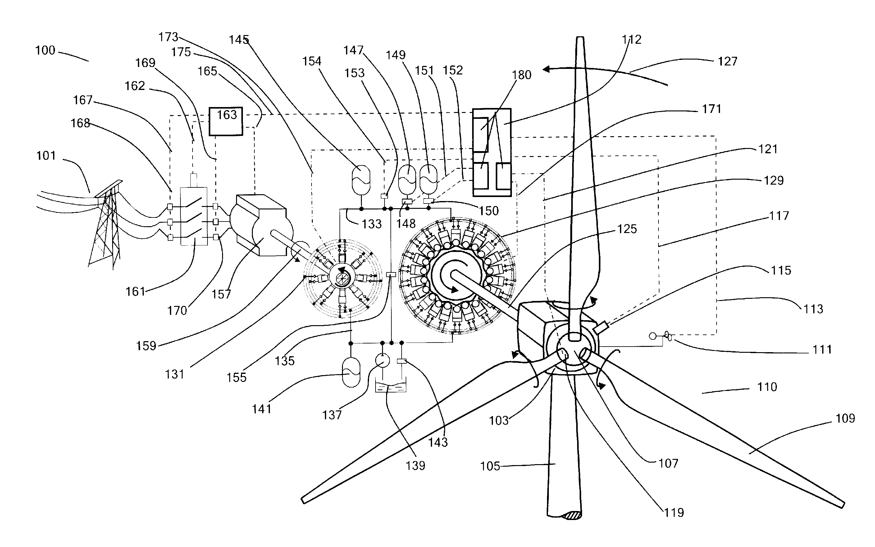
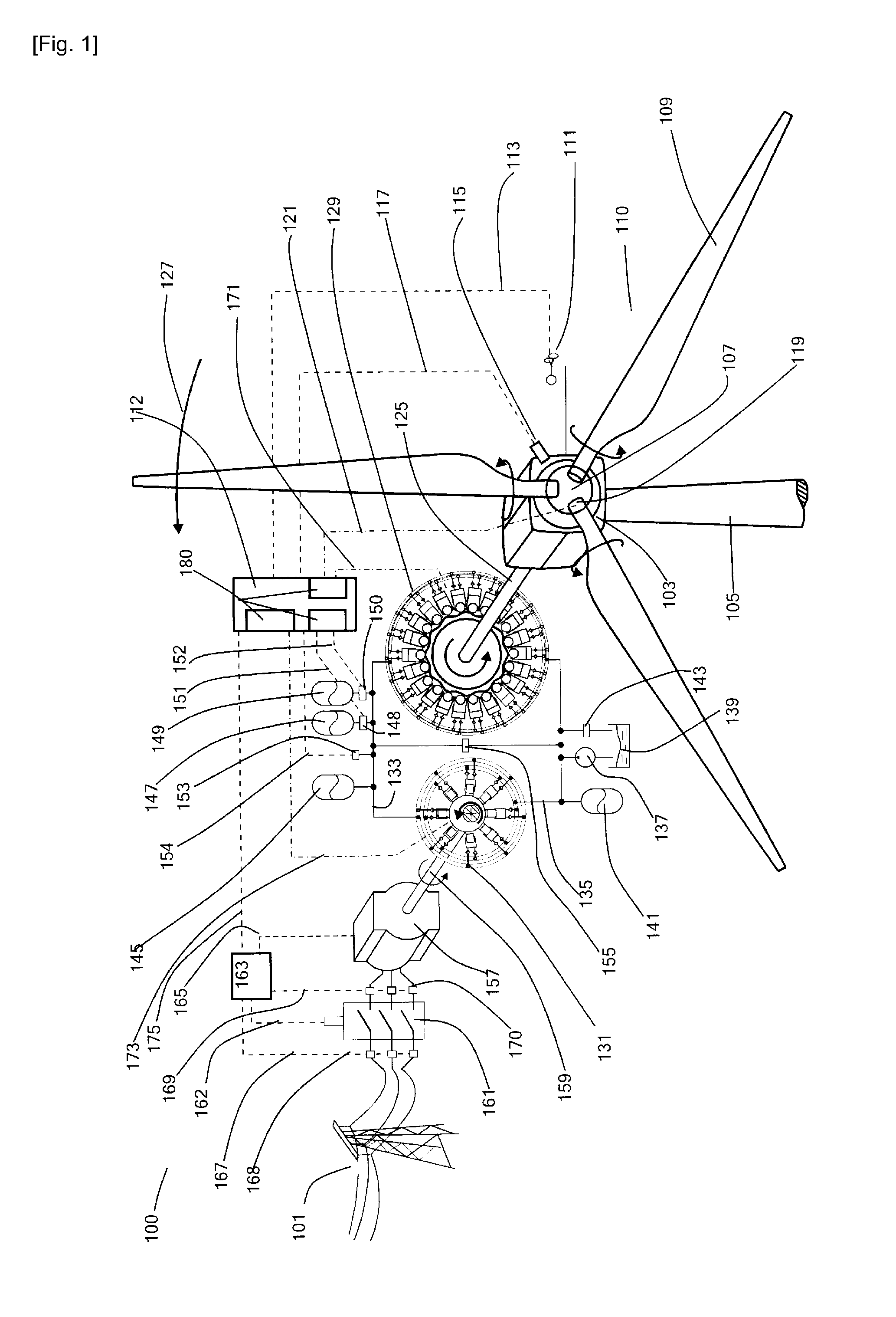
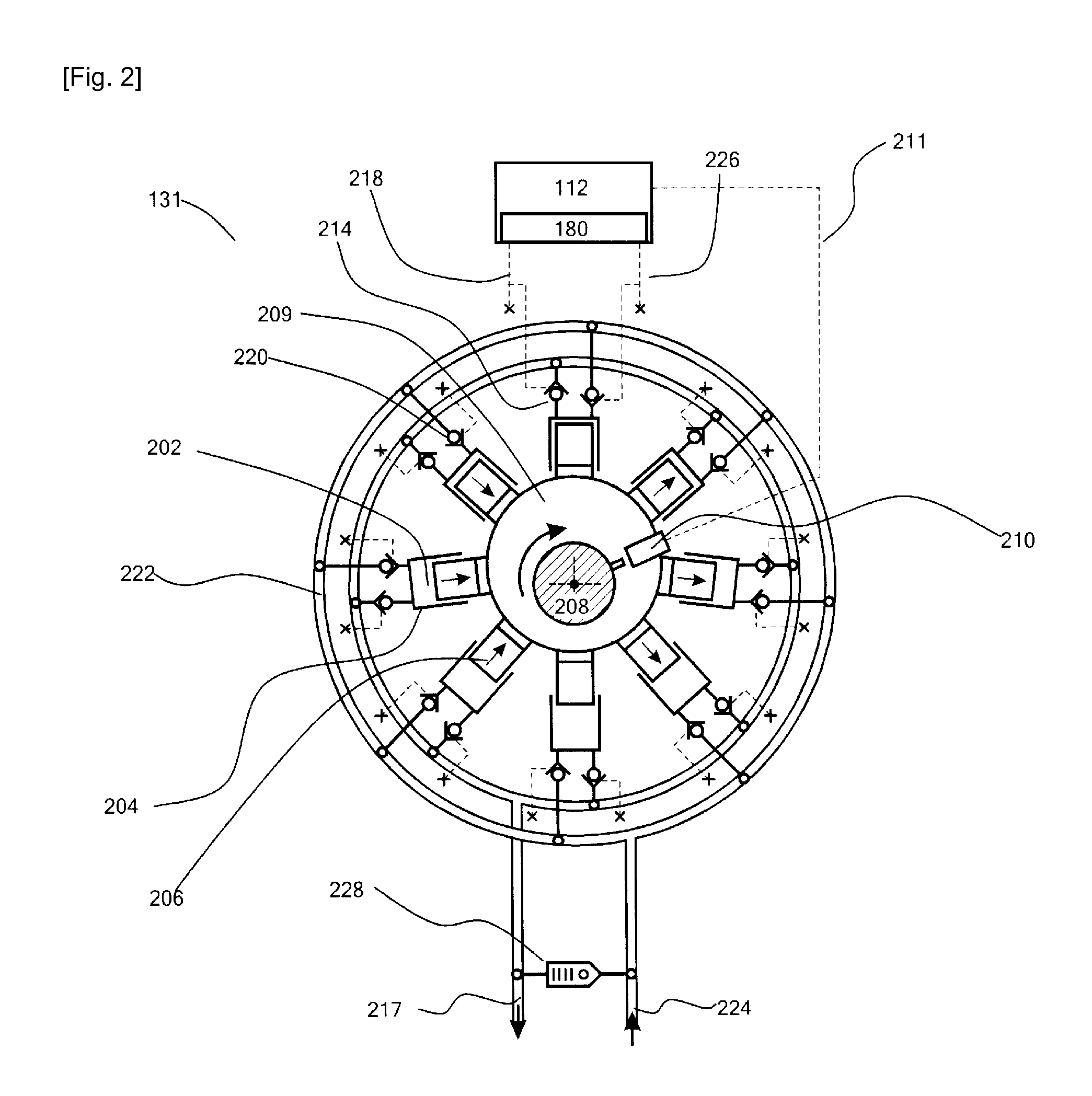
[0054]FIG. 1 illustrates a possible embodiment of the invention in the form of a Wind Turbine Generator (WTG, 100), acting as the energy extraction device, and connected to an electricity network (101). Different layouts providing the same functionality are not ruled out. The WTG comprises a nacelle (103) rotatably mounted to a tower (105) and having mounted thereon a hub (107) supporting three blades (109) known collectively as the rotor (110). An anemometer (111) attached externally to the nacelle provides a measured wind speed signal (113) to a controller (112). A rotor speed sensor (115) at the nacelle provides the controller with a rotor speed signal (117, acting in some embodiments as the fault event sensor). In the example system the angle of attack of each of the blades to the wind can be varied by a pitch actuator (119), which exchanges pitch actuation signals and pitch sensing signals (121) with the controller. The invention could be applied to a WTG without a pitch actuat...


PUM


Abstract

The invention provides a method of operating an energy extraction device such as a wind turbine comprising a hydraulic pump driven by and applying torque to a rotating shaft, a hydraulic motor driving a load, a high pressure manifold in fluid communication with an outlet of the hydraulic pump and an inlet of the hydraulic motor and being selectively placed in fluid communication with a fluid accumulator, at least one low pressure manifold in fluid communication with an outlet of the hydraulic motor and an inlet of the hydraulic pump, at least one of the hydraulic pump or hydraulic motor is a digital hydraulic machine, characterised by interrupting fluid communication between the fluid accumulator and the high pressure manifold responsive to detection of a fault event.

Description

TECHNICAL FIELD [0001]The invention concerns renewable energy devices such as wind turbine generators (WTGs).BACKGROUND ART [0002]Renewable energy devices such as wind turbine generators and tidal stream generators are increasingly important sources of power for AC electricity networks. Such devices traditionally employ a transmission in the form of a gearbox to change the slow input speed of an energy extraction mechanism such as the rotor of a wind or tidal turbine into a fast output speed to drive a generator. Such gearboxes are challenging to design and build as they are prone to failure and expensive to maintain and replace or repair.[0003]It has therefore been proposed to build transmissions for renewable energy devices using fluid working machines, it being possible to make such hydrostatic transmissions variable ratio even at large scales. Such a hydrostatic transmission is also lighter and more robust than a gearbox, and lighter than a direct generator drive, which would ot...

Claims


Application Information

Patent Timeline
IPC IPC(8): F03D9/00F15B20/00F03D9/02
CPCF03D9/001F03D9/003F03D11/02F05B2260/406F16H39/02Y02E10/725Y02E60/17F03D9/028F15B20/007Y02E10/722F03D9/17F03D15/00F03D9/28F03D9/255Y02E10/72Y02E60/16Y02P80/10Y02E70/30F03D9/00
Inventor RAMPEN, WILLIAM
Owner MITSUBISHI HEAVY IND LTD
Learn More