Floating scroll seal with retaining ring

a scroll seal and floating technology, applied in the direction of machines/engines, rotary/oscillating piston pump components, liquid fuel engines, etc., can solve the problems of sealing springs being undetectedly ejected from the seal jacket, sealing to move up, etc., to limit the effect of pressure imbalan

Active Publication Date: 2013-09-26
BITZER KUEHLMASCHINENBAU GMBH
View PDF7 Cites 13 Cited by
  • Summary
  • Abstract
  • Description
  • Claims
  • Application Information

AI Technical Summary

Benefits of technology

[0008]To rectify the problems relating to the pressure imbalance and movement of the seals between the fixed compressor member and the separator plate, embodiments of the present invention aim to limit the effects of the pressure imbalance. In one embodiment, a device is provided that limits the axial movement of the seal relative to the fixed compressor member.
[0009]In a more particular implementation, a new and improved scroll compressor is provided that limits the axial motion of the seal. In particular, in one embodiment, a scroll compressor including a housing, a separator, a fixed scroll body and a floating seal arrangement is provided. The housing defines an internal cavity. The separator is positioned within the internal cavity of the housing and separates a high pressure chamber from a low pressure chamber. The separator includes a port fluidly communicating with the high pressure chamber. The fixed scroll body is positioned within the low pressure chamber and includes a base, a scroll rib axially extending from a first side of the base, and an axially extending circular hub axially on a second opposite side of the base. The circular hub defines a compression outlet extending through the circular hub and fluidly communicates with the high pressure chamber through the port. The floating seal arrangement is interposed between the fixed scroll body and the separator. The floating seal arrangement seals the compression outlet to the port and is axially moveable relative to the circular hub. The floating seal arrangement includes a floating seal; a first seal interface between the separator and the floating seal; and a second seal interface between the floating seal and the circular hub. The second seal interface includes a first seal member interposed between the circular hub and the floating seal. A seal retaining ring is provided to limit axial movement of the first seal member relative to the circular hub in an axial direction extending away from the base. The seal retaining ring prevents axial motion of the first seal member to prevent degradation of the seal of the first seal interface during initial start-up.
[0010]In a more particular embodiment, the floating seal is configured for axial motion relative to the circular hub while remaining in sealing engagement with the first seal member. This allows for increased sealing of the first seal interface and to compensate for thermal expansion / contraction as well as manufacturing tolerances.
[0025]In one embodiment, the fixed scroll body includes a peripheral rim that is spaced radially outward from and circumscribes the circular hub forming an annular channel therebetween. The floating seal extending axially into the annular channel. The scroll compressor further includes a third seal interface between the floating seal and the peripheral rim. The third seal interface including a second seal member radially interposed between the floating seal and the peripheral rim. The third seal interface permits axial motion between the peripheral rim and the floating seal.
[0027]A method of operating a scroll compressor is also provided. The method provides improved operation that prevents the seal between the fixed scroll body from coming apart due to the pressure differential across the seal interface between the floating seal and the fixed scroll body during startup and the transient pressure state present therein. More particularly, one method includes initiating operation of the scroll compressor; applying a first pressure differential in a first direction for an initial period of time across a seal member sealingly interposed between a fixed scroll body and a floating seal, the first pressure differential biasing the first seal member in a first biased direction. The method further including limiting motion of the first seal member in the first biased direction. The method further includes and applying a second pressure differential across the seal member in a second direction opposite the first direction, subsequent to applying the first pressure differential.

Problems solved by technology

This pressure imbalance causes the seal to move up and a seal spring carried within a seal jacket can be undesirably ejected from the seal jacket.

Method used


Image

  • Floating scroll seal with retaining ring
  • Floating scroll seal with retaining ring
  • Floating scroll seal with retaining ring

Examples


Embodiment Construction

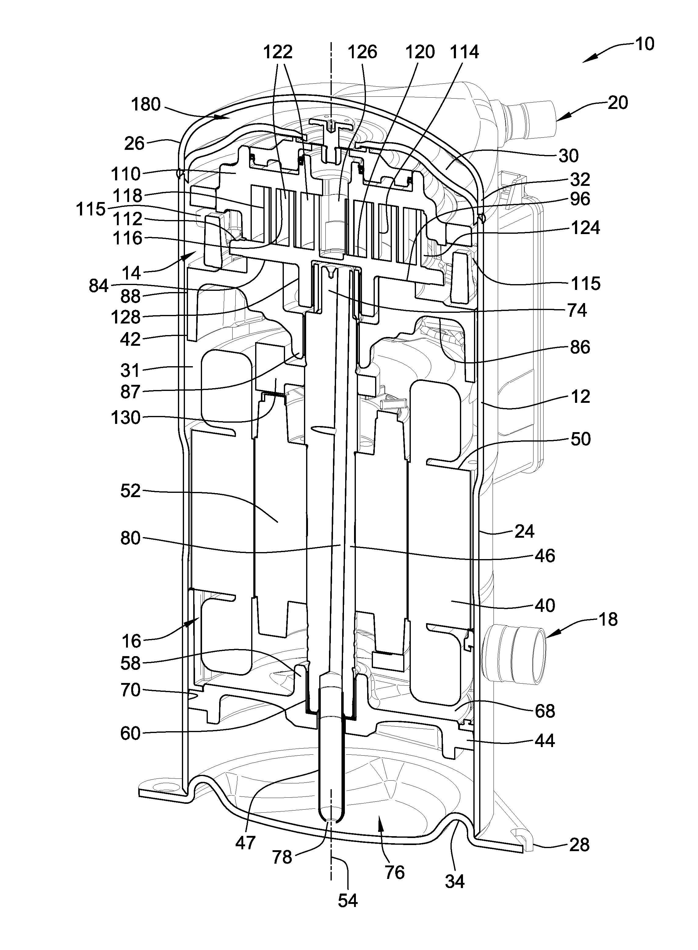
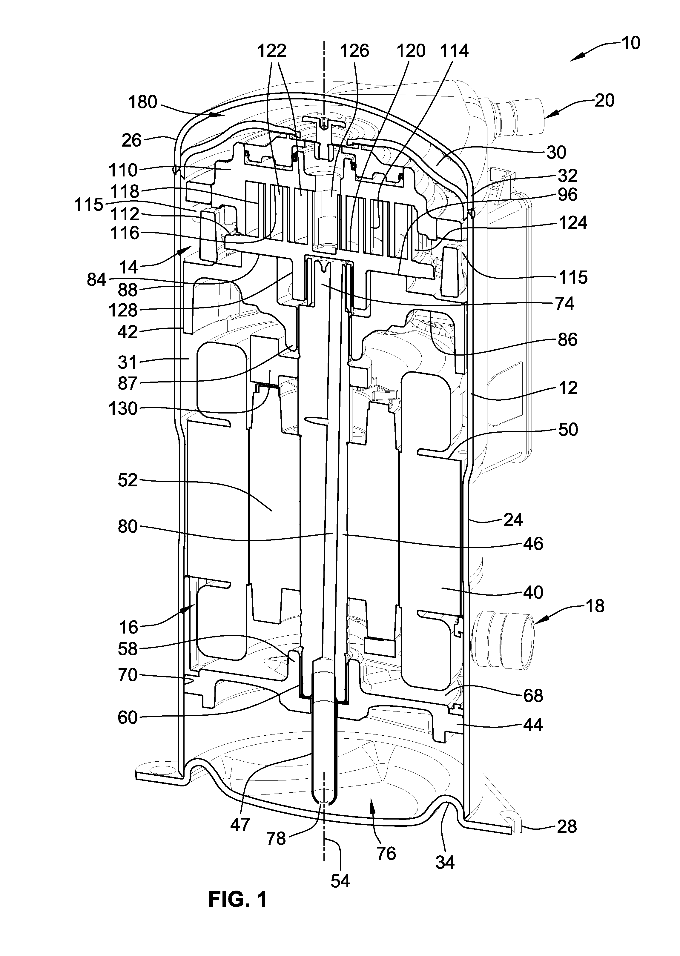
[0048]An embodiment of the present invention is illustrated in the figures as a scroll compressor assembly 10 generally including an outer housing 12 in which a scroll compressor 14 can be driven by a drive unit 16. The scroll compressor assembly 10 may be arranged in a refrigerant circuit for refrigeration, industrial cooling, freezing, air conditioning or other appropriate applications where compressed fluid is desired. Appropriate connection ports provide for connection to a refrigeration circuit and include a refrigerant inlet port 18 and a refrigerant outlet port 20 extending through the outer housing 12. The scroll compressor assembly 10 is operable through operation of the drive unit 16 to operate the scroll compressor 14 and thereby compress an appropriate refrigerant or other fluid that enters the refrigerant inlet port 18 and exits the refrigerant outlet port 20 in a compressed high-pressure state.

[0049]The outer housing for the scroll compressor assembly 10 may take many ...


PUM


Abstract

A scroll compressor that includes a housing and scroll compressor bodies disposed in the housing as well as a method of operation thereof is provided. The housing is separated into different chambers by a separator. One of the scroll bodies is sealed to the separator with a floating seal arrangement including a seal interface between a floating seal of the floating seal arrangement and a hub of a fixed scroll compressor body. A seal retaining ring prevents axial motion of a seal member of the seal interface during start-up operations due to pressure imbalances across the seal member.

Description

FIELD OF THE INVENTION[0001]The present invention generally relates to scroll compressors for compressing refrigerant and more particularly to scroll compressors including a floating seal arrangement interacting with a fixed scroll.BACKGROUND OF THE INVENTION[0002]A scroll compressor is a certain type of compressor that is used to compress refrigerant for such applications as refrigeration, air conditioning, industrial cooling and freezer applications, and / or other applications where compressed fluid may be used. Such prior scroll compressors are known, for example, as exemplified in U.S. Pat. Nos. 6,398,530 to Hasemann; 6,814,551, to Kammhoff et al.; 6,960,070 to Kammhoff et al.; and 7,112,046 to Kammhoff et al., all of which are assigned to a Bitzer entity closely related to the present assignee. As the present disclosure pertains to improvements that can be implemented in these or other scroll compressor designs, the entire disclosures of U.S. Pat. Nos. 6,398,530; 7,112,046; 6,81...

Claims


Application Information

Patent Timeline
Patent Type & Authority Applications(United States)
IPC IPC(8): F01C1/02
CPCF01C17/066F01C19/005F01C21/007F04C18/0253F04C29/126F04C18/0215F04C2230/60F04C23/008F04C29/12
Inventor ROOF, JOHNATHAN P.DUPPERT, RONALD J.
Owner BITZER KUEHLMASCHINENBAU GMBH
Why Eureka
Try Eureka