
Battery and battery system

a battery and battery technology, applied in the field of batteries, can solve the problems of large amount of high-temperature gas generated in the battery container, battery container body explosion, chain reaction,

Inactive Publication Date: 2013-09-26
MITSUBISHI HEAVY IND LTD
View PDF2 Cites 10 Cited by
  • Summary
  • Abstract
  • Description
  • Claims
  • Application Information

AI Technical Summary

Benefits of technology

The patent describes a battery design that includes a safety valve to prevent gas from being discharged directly to objects, which could cause a chain reaction and damage the battery. The safety valve guides the gas in a way that prevents it from affecting the objects, resulting in a safer and more stable battery.

Problems solved by technology

In batteries such as lithium secondary batteries, for example, there are concerns that when problems such as a short or an overcharge occur, a large amount of high-temperature gas is generated in the battery container due to the rapid evaporation of the electrolyte and the like and an internal pressure of the battery container rapidly increases, whereby a battery container body explodes.
As a result, there is a possibility that a chain reaction may be caused in which a battery disposed on the upper shelf is also heated and the internal pressure thereof also increases, whereby a safety valve operates.

Method used


Image

  • Battery and battery system
  • Battery and battery system
  • Battery and battery system

Examples


first embodiment

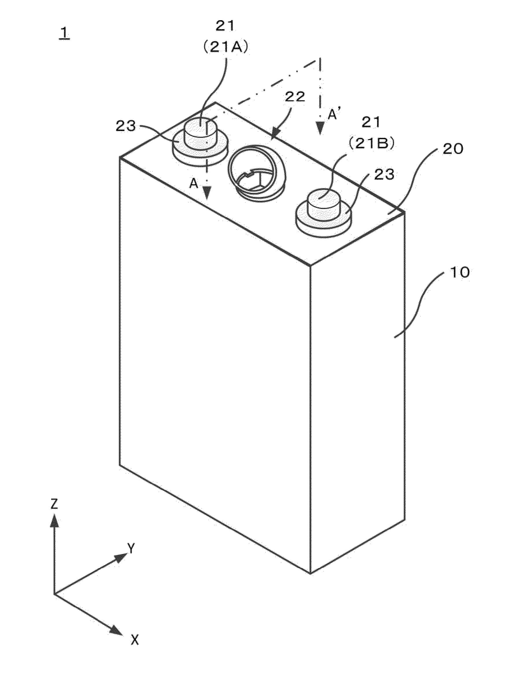
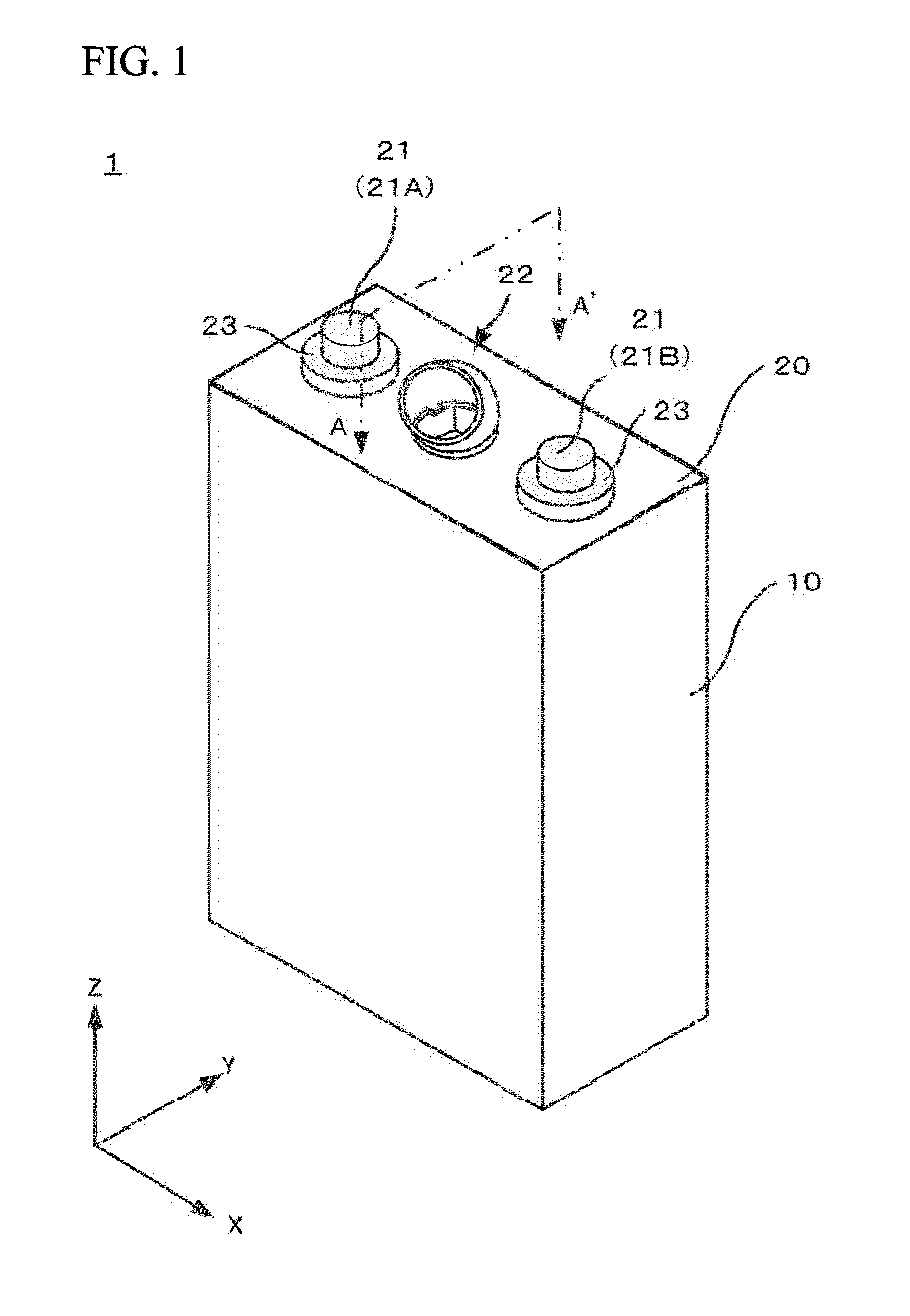
[0030]FIG. 1 illustrates a schematic perspective view of a battery 1 according to a first embodiment of the present invention.

[0031]The battery 1 according to the first embodiment of the present invention is as shown in FIG. 1, and is constituted by a battery container body 10 and a battery lid 20 which covers an opening of the battery container body 10 and has two electrode terminals 21 (positive electrode terminal 21A and negative electrode terminal 21B) and a safety valve (valve unit) 22 disposed thereon. Hereinafter, the battery container body 10 formed integrally with the battery lid 20 will be referred to as the “battery container”.

[0032]The battery container body (body of the battery container) 10 is an angular container which accommodates an electrode plate, that is, a laminated electrode body (not shown) having a positive electrode plate and a negative electrode plate laminated with a separator interposed therebetween, together with an electrolyte and the like. The battery ...

modified examples

[0048]As described above, the preferred embodiments of the battery and the battery system of the invention have been described. However, the invention is not limited to the above-described embodiments, and various modifications, additions, and omissions can be made by those skilled in the art without departing from the spirit and scope represented in the claims.

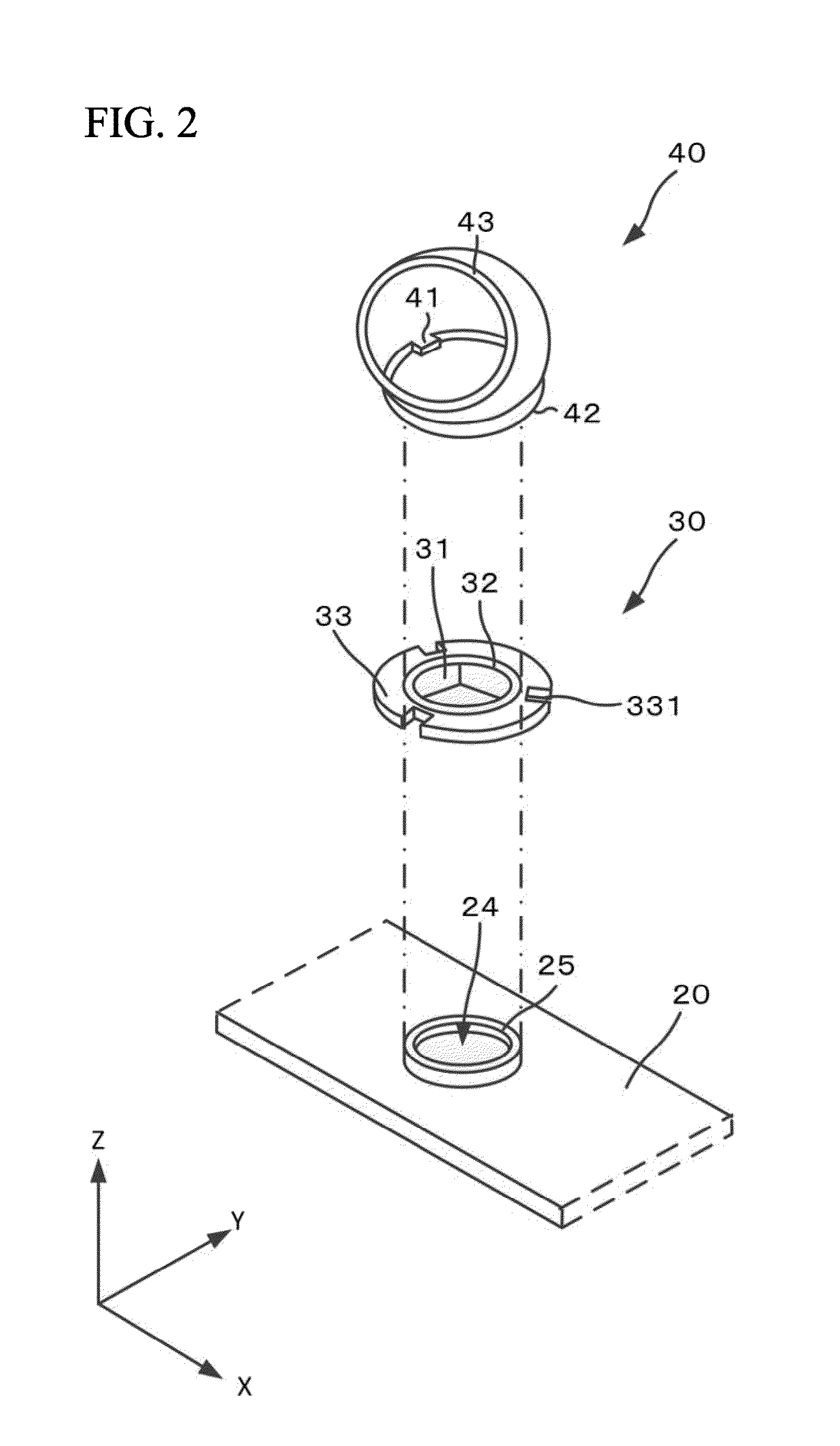
[0049]For example, in the above-described embodiments, the case in which the second joining section 33 of the break part 30 and the height 41 of the guide 40 are joined to each other, and thus the break part 30 and the guide 40 are joined to each other has been described as an example. However, the invention is not limited thereto, and the guide 40 may be directly joined to the battery lid 20. For example, as shown in FIG. 6, in a columnar protrusion which protrudes from the peripheral edge of the through hole 24 of the battery lid 20 to the outside of the battery container (+Z direction), a joining section (for example, male...


PUM

PropertyMeasurementUnit
angleaaaaaaaaaa
thicknessaaaaaaaaaa
pressureaaaaaaaaaa

Abstract

A battery includes a valve unit which is disposed on a first surface of a battery container to be broken when a gas pressure in the battery container increases to a predetermined value or greater, so as to guide a gas in the battery container in a direction inclined at a predetermined angle with respect to a normal direction of the first surface to discharge the gas to the outside.

Description

BACKGROUND OF THE INVENTION[0001]1. Field of the Invention[0002]The present invention relates to a battery, and particularly, to a safety valve which is provided in the battery.[0003]Priority is claimed on Japanese Patent Application No. 2012-065229, filed on Mar. 22, 2012, the content of which is incorporated herein by reference.[0004]2. Description of Related Art[0005]As batteries, there are primary batteries which perform only discharge and secondary batteries which perform discharge and charge. Particularly, in recent years, attention has been paid to lithium secondary batteries having features such as a high energy density, a high output, and a long lifespan as secondary batteries. Generally, the lithium secondary batteries have a configuration in which a laminated electrode body having a positive electrode plate and a negative electrode plate laminated with a separator interposed therebetween is sealed in a battery container together with an electrolyte and the like.[0006]In b...

Claims


Application Information

Patent Timeline
Patent Type & Authority Applications(United States)
IPC IPC(8): H01M2/12
CPCF16K17/00H01M2/1241F16K17/16H01M50/3425Y02E60/10
Inventor CHIBA, DAISUKE
Owner MITSUBISHI HEAVY IND LTD
Learn More