Connection structure of electric wire and terminal, and manufacturing method thereof

Active Publication Date: 2013-09-26
YAZAKI CORP
View PDF13 Cites 24 Cited by
  • Summary
  • Abstract
  • Description
  • Claims
  • Application Information

AI Technical Summary

Benefits of technology

[0029]In the connection structure of the electric wire and the terminal according to the sixth aspect of the invention, while having an effect similar to the first aspect of the invention described above, the first crimp part is formed so as to increase the cross-sectional area orthogonal to the extension direction of the electric wire surrounded by the first crimp part, so that the insulating part is prevented from swelling in the vicinity of the portion of crimping the first crimp part and a thickness of the seal part is prevented from becoming thin in this swelling portion, so that waterproof properties can be increased, with the result that corrosion-proof properties can be improved.
[0030]In the connection structure of the electric wire and the terminal according to the seventh aspect of the invention, while having an effect similar to the first aspect of the invention described above, the structure is constructed so as to increase the cross-sectional area orthogonal to the extension direction of the electric wire surrounded by the first crimp part, so that the insulating part is prevented from swelling in the vicinity of the portion of crimping the first crimp part and a thickness of the seal part is prevented from becoming thin in this swelling portion, so that waterproof properties can be increased, with the result that corrosion-proof properties can be improved.
[0031]In the connection structure of the electric wire and the terminal according to the eighth aspect of the invention, while having an effect similar to the first aspect of the invention described above, also in the case of using aluminum in the conductor part, peeling of the seal part can be prevented to increase waterproof properties, with the result that corrosion-proof properties can be improved.
[0032]Since the manufacturing method of the connection structure of the electric wire and the terminal according to the ninth aspect of the invention forms the seal part which is made of thermoplastic elastomer and covers the surface including the first crimp part and the insulating coated part of the side extending from the first crimp part toward the dir

Problems solved by technology

On the other hand, the automobile industry has a problem important to improve fuel efficiency by reducing vehicle weight out of consideration for environment.
However, aluminum tends to corrode in the

Method used


Image

  • Connection structure of electric wire and terminal, and manufacturing method thereof
  • Connection structure of electric wire and terminal, and manufacturing method thereof
  • Connection structure of electric wire and terminal, and manufacturing method thereof

Examples


first embodiment

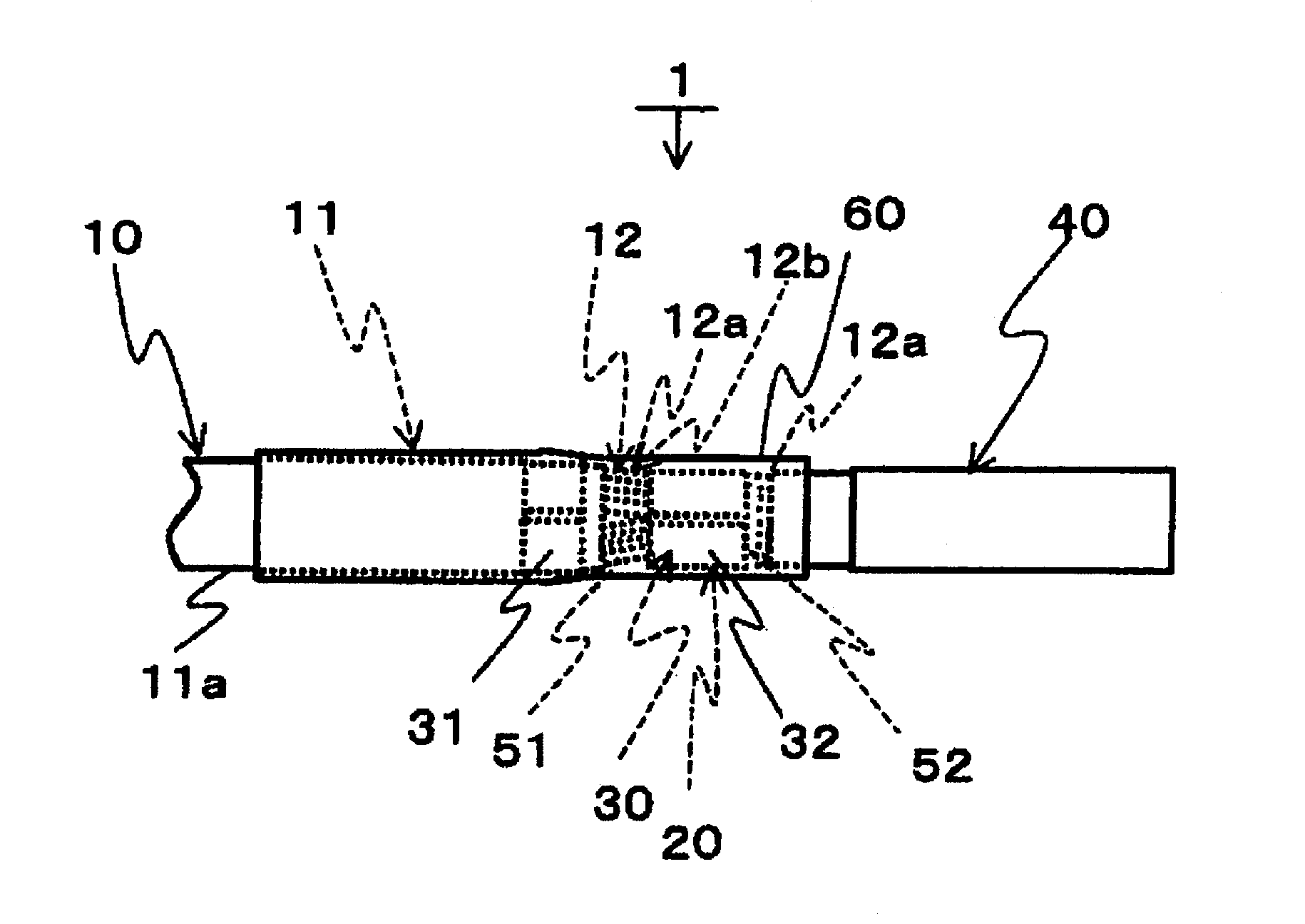
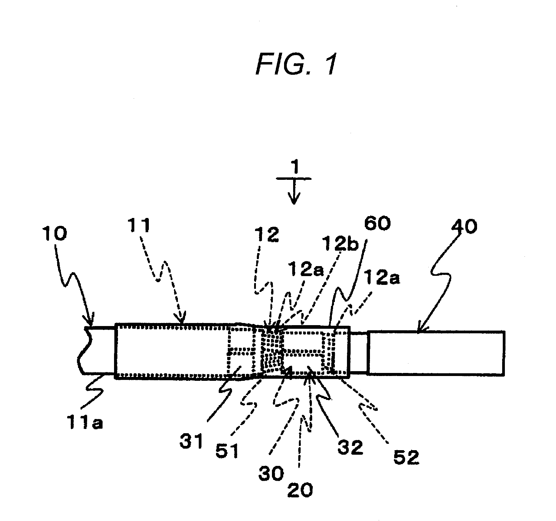
[0061]FIG. 1 is a plan view showing a connection structure 1 of an electric wire and a terminal according to a first embodiment of the invention. FIG. 2 is a side view showing the connection structure 1 of the electric wire and the terminal according to the embodiment of the invention. The connection structure 1 of the electric wire and the terminal has an electric wire 10, a terminal 20 and a seal part 60.

[0062]The electric wire 10 has an insulating coated part 11 and a conductor exposed part 12.

[0063]The insulating coated part 11 is the portion in which a conductor part 12b obtained by bundling plural core wires 12a made of an aluminum material is coated with an insulating part 11a made of an insulating material such as polypropylene (PP). In addition, the insulating part 11a is not limited to polypropylene and other insulating materials may be used.

[0064]The conductor exposed part 12 is the portion in which the insulating part 11a of the end of the electric wire 10 is removed and...

second embodiment

[0085]Next, a manufacturing method of a connection structure 1 of an electric wire and a terminal of a second embodiment of the invention will be described using FIGS. 6A to 8. FIGS. 6A and 6B are diagrams describing a state of a seal part 60 by separation of a gate 71a in the case of arranging a position of the gate 71a of a metallic mold 70 in the vicinity of the end of the seal part 60. FIG. 7 is a diagram showing the metallic mold 70 in which the position of the gate 71a used in the manufacturing method of the connection structure 1 of the electric wire and the terminal of the second embodiment of the invention is displaced, and the connection structure 1 of the electric wire and the terminal. FIG. 8 is a diagram showing one example of the displaced position of the gate 71a. In addition, in FIGS. 6A and 6B, a diagram arranged in the right side is a main sectional view of the diagram arranged in the left side.

[0086]Also, the same numerals are assigned to the same components as th...

third embodiment

[0092]Next, a third embodiment of the invention will be described using FIGS. 9 and 10. FIG. 9 is a diagram showing a structure 2 of connection between an electric wire and a terminal of the third embodiment of the invention. FIG. 10 is a sectional view taken on line B-B of the structure 2 of connection between the electric wire and the terminal shown in FIG. 9.

[0093]Also, the same numerals are assigned to the same components as those of the first and second embodiments described above.

[0094]The structure 2 of connection between an electric wire 10 and a terminal 21 of this third embodiment has a configuration of preventing occurrence of peeling in the vicinity of the gate 71a described in the second embodiment. In the structure 2 of connection between the electric wire 10 and the terminal 21, a rectangular opening part 21a is formed in the terminal 21 as shown in FIG. 9.

[0095]The opening parts 21a are formed in side walls 21b, 21b covered with a seal part 60. More concretely, the o...


PUM

PropertyMeasurementUnit
Adhesion strengthaaaaaaaaaa
Shapeaaaaaaaaaa
aaaaaaaaaa

Abstract

A connection structure of an electric wire and a terminal includes the electric wire, the terminal, and a seal part. The electric wire has an insulating coated part in which a conductor part is covered with an insulating material, and a conductor exposed part in which the insulating material of an end of the electric wire is removed. The terminal includes a first crimp part crimped to the insulating coated part, and a second crimp part crimped to the conductor exposed part. The seal part is made of thermoplastic elastomer and covers a surface including the first crimp part and the insulating coated part of a side extending from said first crimp part toward a direction opposite to the end of the electric wire and a surface of the second crimp part in an extension direction of the electric wire.

Description

CROSS REFERENCE TO RELATED APPLICATION[0001]This application is a continuation of PCT application No. PCT / JP2011 / 077871, which was filed on Nov. 25, 2011 based on Japanese Patent Applications Nos. 2010-263601 filed on Nov. 26, 2010, and 2011-009438 filed on Jan. 20, 2011, the contents of which are incorporated herein by reference.BACKGROUND OF THE INVENTION[0002]1. Technical Field[0003]The present invention relates to a connection structure of an electric wire and a terminal, and particularly to a connection structure of an electric wire having a core wire made of aluminum and a terminal made of metal different from that of the core wire, and a manufacturing method of the structure of connection.[0004]2. Background Art[0005]A signal line or a power line in which an electric wire having a core wire made of a copper material is connected to a terminal made of a copper material has conventionally been used in an automobile, a home appliance, etc.[0006]On the other hand, the automobile ...

Claims


Application Information

Patent Timeline
IPC IPC(8): H01R4/62H01R43/05
CPCH01R4/185H01R4/62H01R4/72Y10T29/49192H01R43/005H01R43/05H01R13/5216H01R4/70H01R43/28H01R4/18
Inventor TANAKA, SHINYAHANAZAKI, HISASHIKITAGAWA, HIRONORI
Owner YAZAKI CORP
Why Eureka
Try Eureka