Display apparatus

a technology of display apparatus and display plate, which is applied in the direction of optical elements, planar/plate-like light guides, instruments, etc., can solve the problems of weak structural strength of the substrate with a smaller thickness, easy local stress on the glass substrate, and light leakage, so as to effectively eliminate light leakage

Active Publication Date: 2013-10-03
AU OPTRONICS (SUZHOU) CORP LTD +1
View PDF3 Cites 7 Cited by
  • Summary
  • Abstract
  • Description
  • Claims
  • Application Information

AI Technical Summary

Benefits of technology

[0011]In order to solve the problems of the prior art, the disclosure provides an improved display apparatus, in which segmented double-sided adhesive tapes are stuck on a supporting surface of a frame of a backlight module. Furthermore, when a TFT (Thin-Film Transistor) array substrate of a panel module of the display apparatus is mounted to the frame, each of the double-sided adhesive tapes is aligned with a gap between two adjacent chips on the TFT array substrate, so as to effectively eliminate the light leakages occur at locations respectively corresponding to an upper-left corner and an upper-right corner of each of the chips and to prevent a screen of the display apparatus from showing COG mura as much as possible.

Problems solved by technology

However, the glass substrate with a smaller thickness has weak structural strength, and thus the glass substrate is easily affected by local stress due to its weight or the adhesion force of the double-sided adhesive tape in the COG process.
The glass substrate and the chips respectively have different coefficients of expansion, which result in the flexure of the glass substrate and cause light leakages at locations respectively corresponding to an upper-left corner and an upper-right corner of each of the chips.
Furthermore, when the display apparatus encounters an unexpected impact, the edge of the glass substrate may have cracks or notches, or the entire glass substrate may be broken.
Although a thin film made of resin or plastic is considered to substitute the glass substrate, the film-forming temperature is limited, and thus is not practically feasible.

Method used


Image

  • Display apparatus
  • Display apparatus
  • Display apparatus

Examples


Embodiment Construction

[0034]Reference will now be made in detail to the present embodiments of the disclosure, examples of which are illustrated in the accompanying drawings. Wherever possible, the same reference numbers are used in the drawings and the description to refer to the same or like parts.

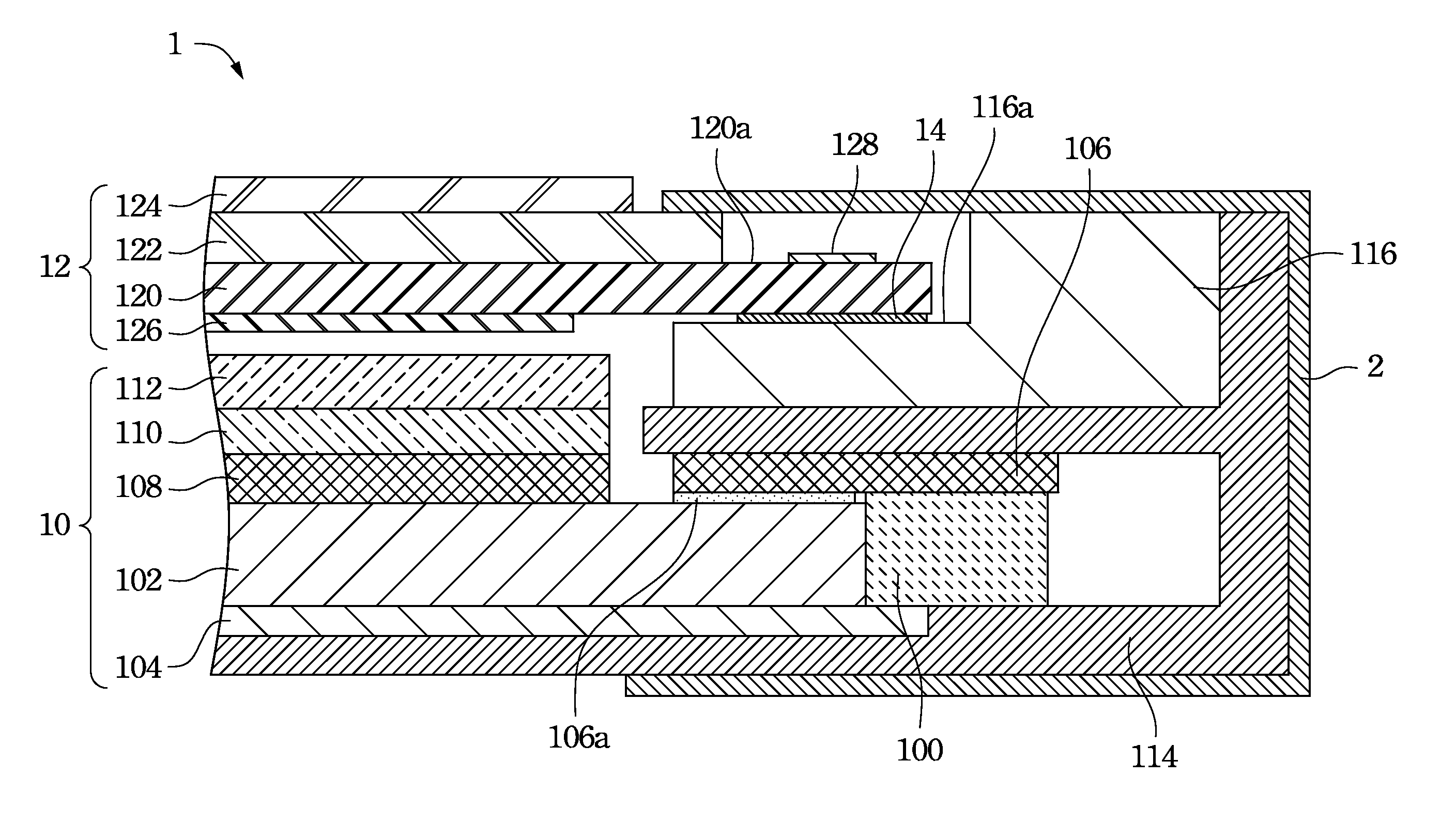
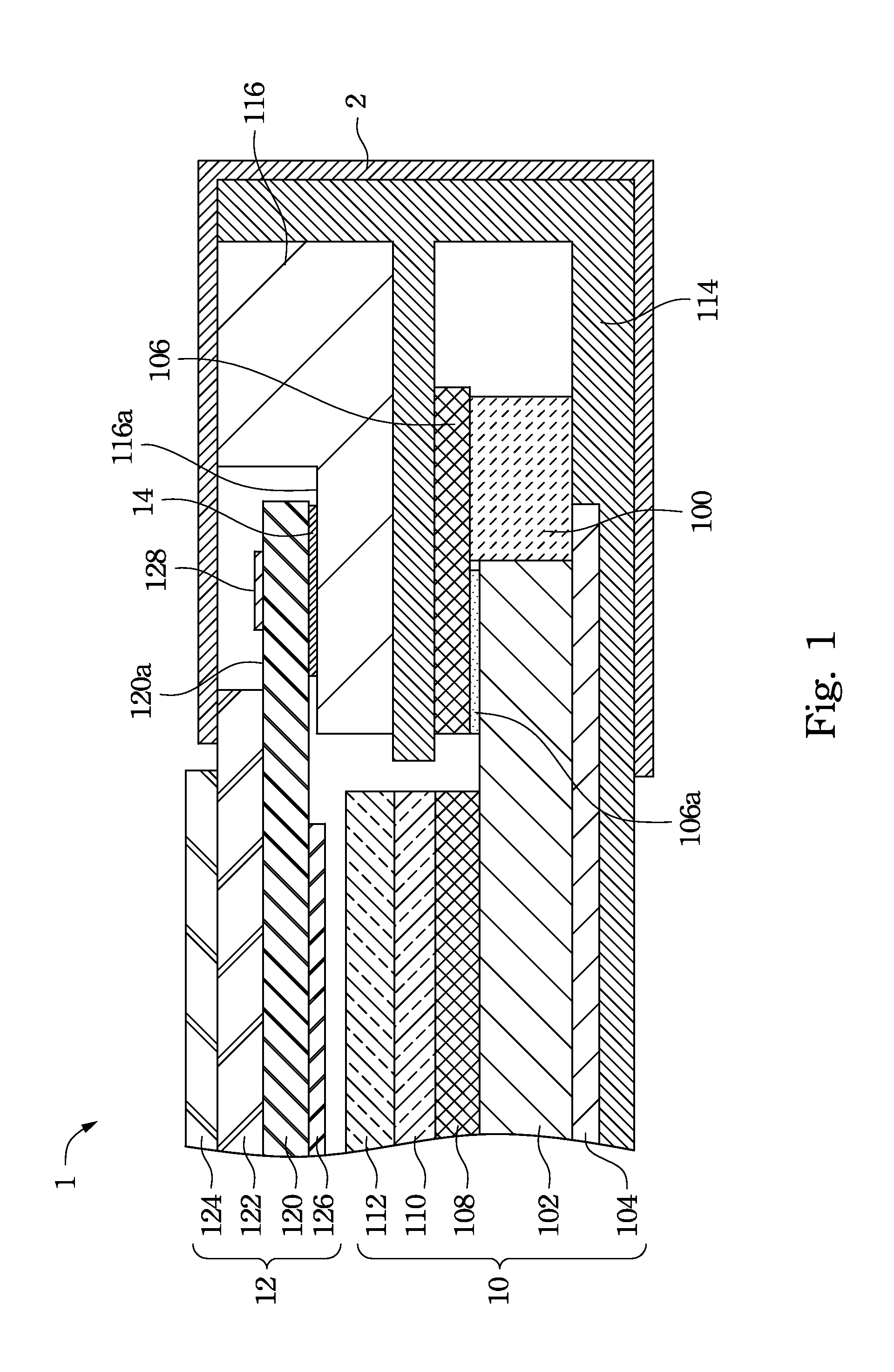
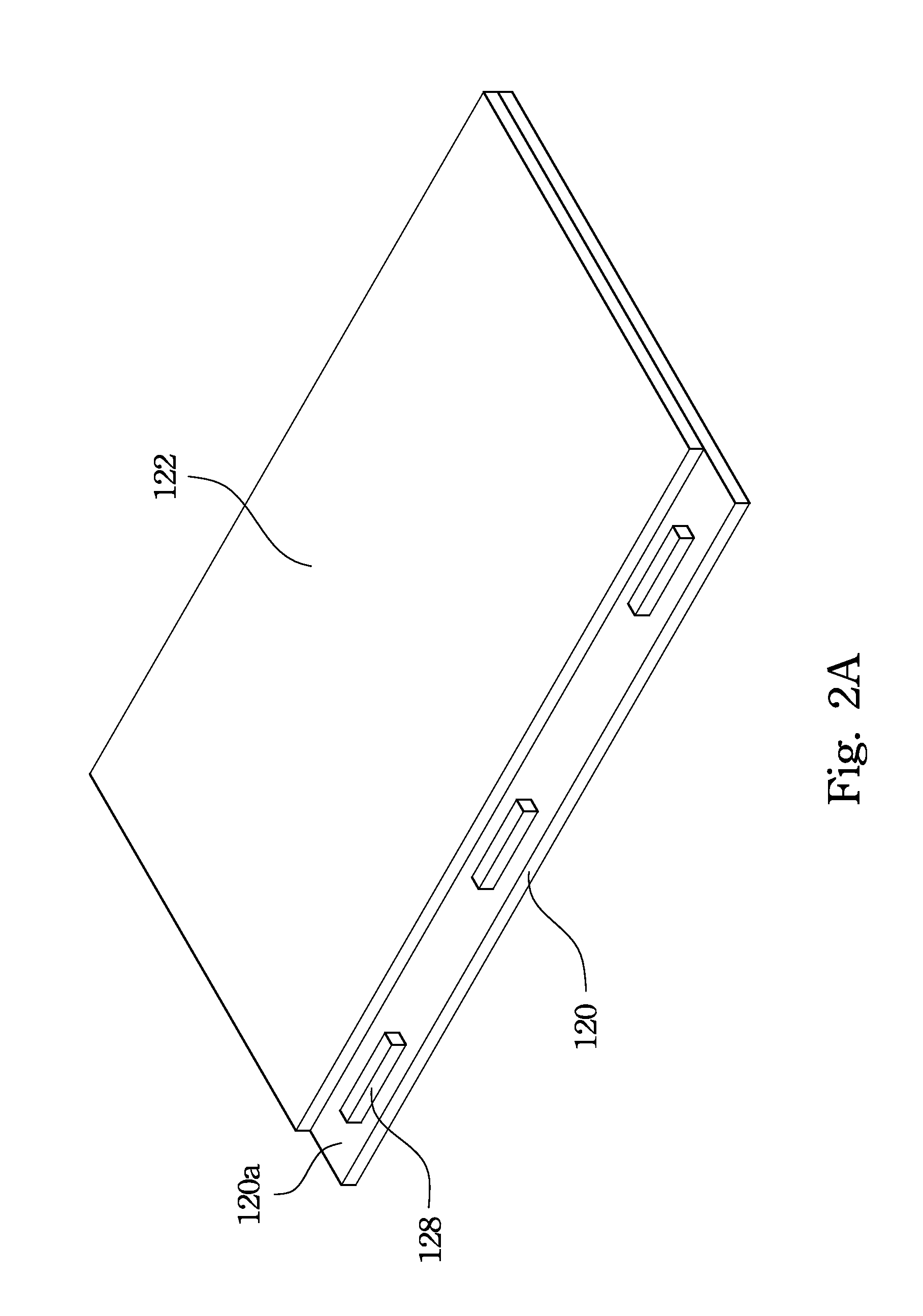
[0035]An improved display apparatus is provided. Specifically, segmented double-sided adhesive tapes are stuck on a supporting surface of a frame of a backlight module. Furthermore, when a TFT (thin-film transistor) array substrate of a panel module of the display apparatus is mounted to the frame, each of double-sided adhesive tapes is aligned with a gap between two adjacent chips on the TFT array substrate, so as to effectively eliminate the light leakages occurring at locations respectively corresponding to an upper-left corner and an upper-right corner of each of the chips and prevent a screen of the display apparatus from showing COG mura as much as possible. The foregoing COG mura is related to a length...


PUM


Abstract

A display apparatus includes a backlight module, a panel module, and a plurality of double-sided adhesive tapes. The backlight module includes a bezel. The frame has a supporting surface. The panel module includes a glass substrate and a plurality of chips. The glass substrate is disposed on the supporting surface. An edge of the glass substrate has a bonding region. The chips are disposed at the bonding region. The chips and the supporting surface are respectively located at two opposite sides of the glass substrate. The double-sided adhesive tapes are disposed between the supporting surface and the bonding region. Each of the double-sided adhesive tapes is aligned with a gap between two adjacent chips.

Description

RELATED APPLICATIONS[0001]This application claims priority to China Application Serial Number 201210099634.8, filed Apr. 1, 2012, which is herein incorporated by reference.BACKGROUND[0002]1. Technical Field[0003]The present disclosure relates to a display apparatus.[0004]2. Description of Related Art[0005]In recent years, owing to the rapid development of the electronics industry and the information industry, their related products also become increasingly sophisticated. For the current personal computers, in addition to seeking more rapid and more powerful computing units and a wide range of peripheral equipments to meet user needs, compact portable computers are the key development area of the industry.[0006]For example, liquid crystal displays have advantages such as high definition, small size, light weight, low driving voltage, low power consumption, and a wide range of applications, and thus can be widely applied in portable televisions, mobile phones, camcorders, notebook com...

Claims


Application Information

Patent Timeline
Patent Type & Authority Applications(United States)
IPC IPC(8): H01L27/15
CPCG02F2001/133317G02F1/133308G02F2202/28H01L27/153G02B6/0091G02B6/0083G02F2001/133314G02F1/133317G02F1/133314
Inventor CHEN, XIANG-CHONGLIN, TUNG-SHINGUO, YUN-TAOTSAI, CHENG-MINLIN, SHIH-PING
Owner AU OPTRONICS (SUZHOU) CORP LTD
Why Eureka
Try Eureka