Multilayer coil component

a multi-layer coil and component technology, applied in the direction of coils, transformers/inductance details, inductances, etc., can solve the problems of insufficient electric field, and reduced mounting strength of the multi-layer coil component, so as to suppress the suppress the foregoing generation of internal structural defects

Active Publication Date: 2013-10-03
TDK CORPARATION
View PDF3 Cites 37 Cited by
  • Summary
  • Abstract
  • Description
  • Claims
  • Application Information

AI Technical Summary

Benefits of technology

[0012]The Inventors newly found by our research study that when the edge of the first connection conductor was relatively close to the edges of the first external electrodes, the stress based on the difference between volume changes during the sintering process could generate an internal structural defect in the insulator layer located between the first connection conductor and the first external electrodes and in the insulator layer located between the second connection conductor and the second external electrodes. In the light of this study result, the first connection conductor is located inside the single region composed of the profiles of the pair of first external electrodes when viewed from the direction normal to the first principal face, whereby the edge of the first connection conductor becomes separated from the edges of the first external electrodes. For this reason, it is feasible to further suppress the generation of internal structural defect discussed above. Similarly, the edge of the second connection conductor becomes separated from the edges of the second external electrodes and therefore it is feasible to further suppress the foregoing generation of internal structural defect.
[0013]A thickness of the insulator layer located between the first connection conductor and the pair of first external electrodes may be larger than a thickness of the first connection conductor, and a thickness of the insulator layer located between the second connection conductor and the pair of second external electrodes may be larger than a thickness of the second connection conductor. In this case, the thickness of the insulator layer located between the first connection conductor and the pair of first external electrodes is set relatively large, which can prevent the internal structural defect from being generated in the insulator layer located between the first connection conductor and the first external electrodes, because of the stress based on the difference between volume changes during the sintering process. The thickness of the insulator layer located between the second connection conductor and the pair of second external electrodes is set relatively large, which can similarly prevent the internal structural defect from being generated in the insulator layer located between the second connection conductor and the second external electrodes.

Problems solved by technology

During execution of electroplating, therefore, an adequate electric field is not applied to the other external electrodes in the electrically floating state, which makes it difficult to form a plated layer thereon.
If the plated layer is not adequately formed (e.g., if the plated layer is too thin), adhesion strength will become weak between the external electrodes and the plated layer, which can cause reduction in mounting strength of the multilayer coil component.

Method used


Image

  • Multilayer coil component
  • Multilayer coil component
  • Multilayer coil component

Examples


Embodiment Construction

[0021]The preferred embodiments of the present invention will be described below in detail with reference to the accompanying drawings. In the description, the same elements or elements with the same functionality will be denoted by the same reference signs, without redundant description.

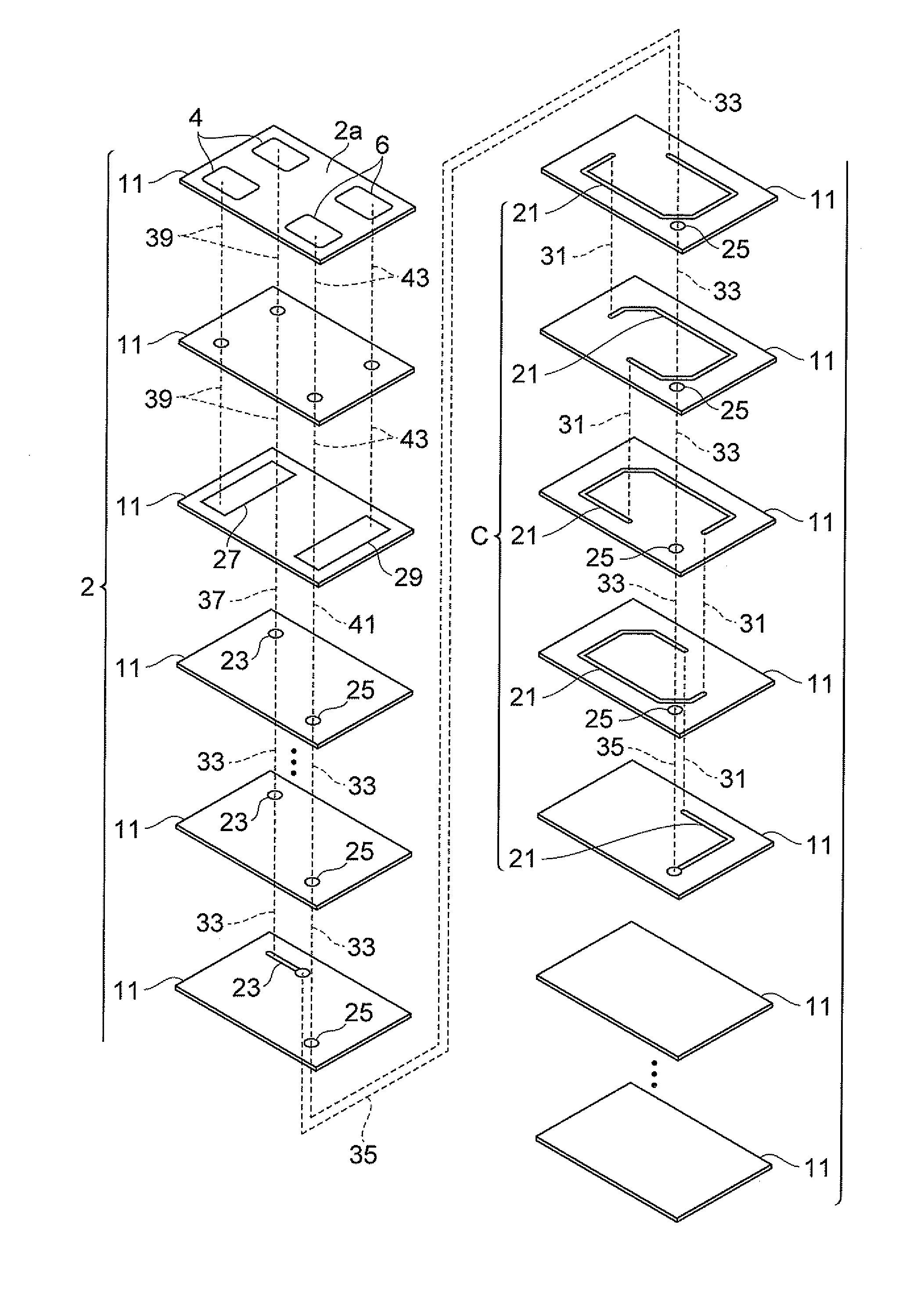
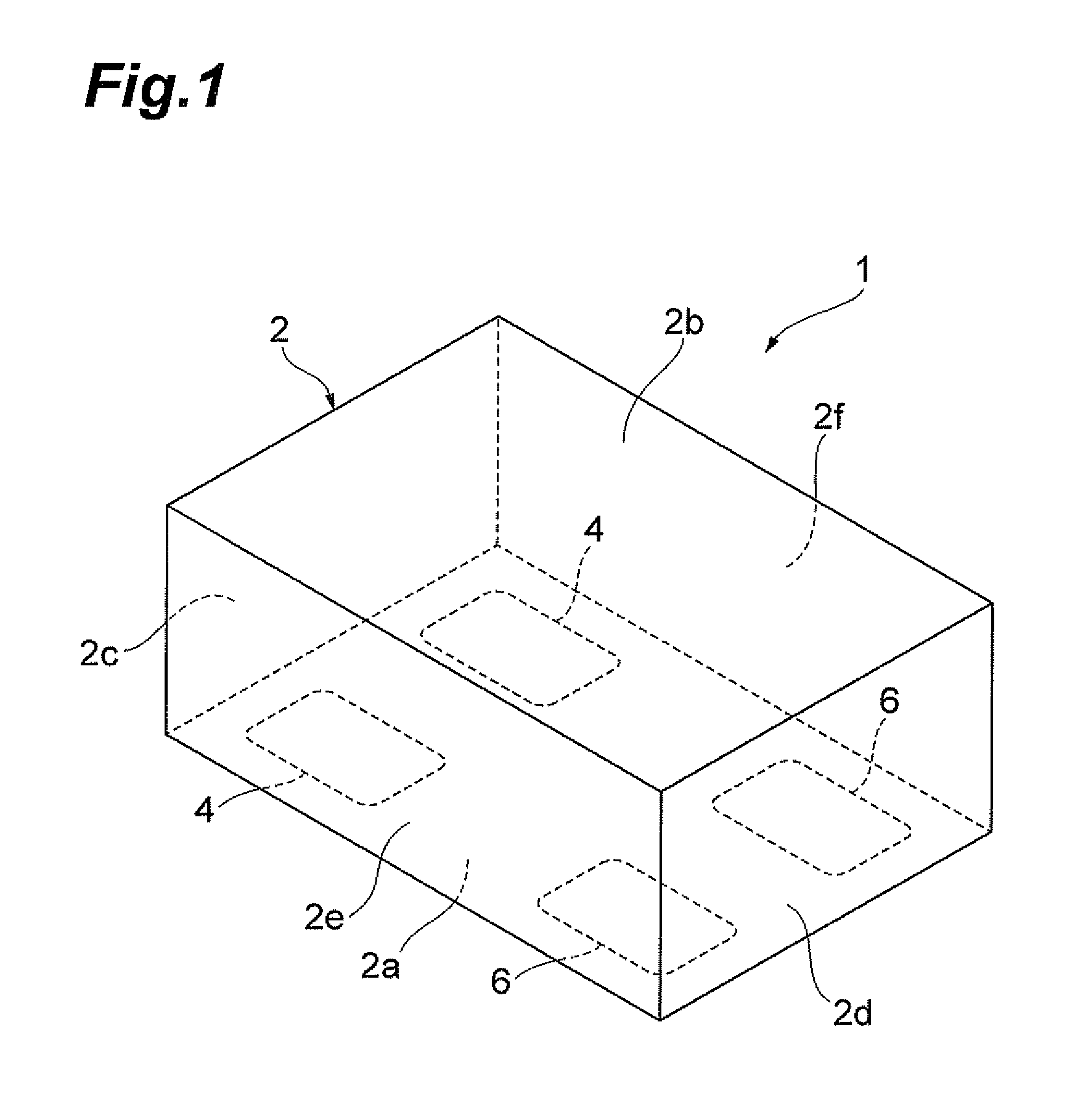
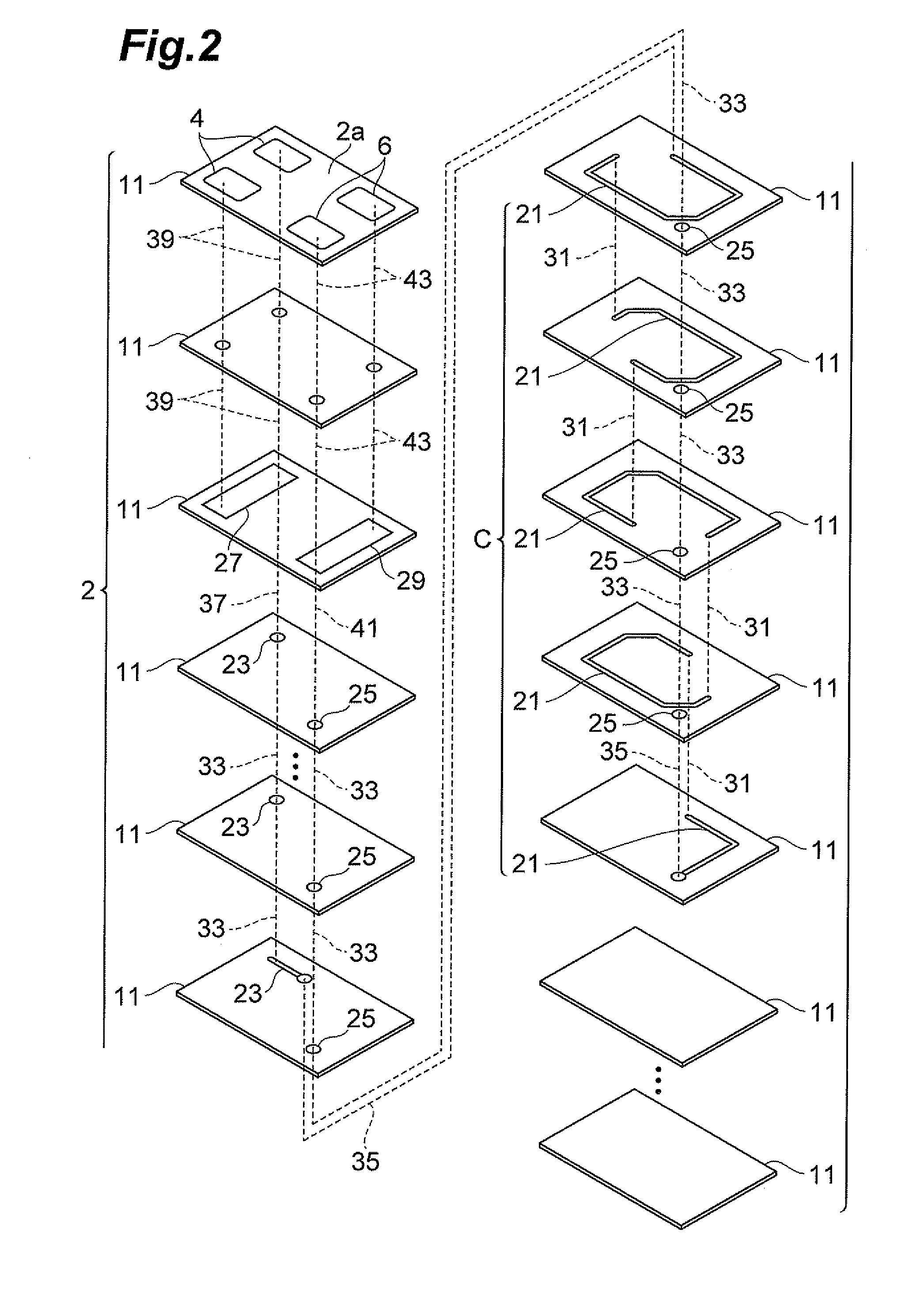
[0022]First, a configuration of a multilayer coil component 1 according to an embodiment of the present invention will be described with reference to FIGS. 1 to 5. FIG. 1 is a perspective view showing the multilayer coil component according to the present embodiment. FIG. 2 is an exploded perspective view showing a configuration of an element body in the multilayer coil component according to the present embodiment. FIGS. 3 and 4 are drawings for explaining respective sectional configurations of the element body in the multilayer coil component according to the present embodiment. FIG. 5 is a drawing for explaining locations of first and second external electrodes and first and second connection con...


PUM

PropertyMeasurementUnit
areaaaaaaaaaaa
thicknessaaaaaaaaaa
electrically floating stateaaaaaaaaaa

Abstract

A multilayer coil component has an element body, a coil, a pair of first external electrodes, a pair of second external electrodes, a first connection conductor, and a second connection conductor. The coil is composed of a plurality of internal conductors arranged in the element body and connected to each other. The first external electrodes are arranged on a first principal face of the element body. The second external electrodes are arranged on the first principal face. The first connection conductor is arranged between the coil and the first external electrodes in the element body and is connected to one end of the coil and to the first external electrodes. The second connection conductor is arranged between the coil and the second external electrodes in the element body and is connected to the other end of the coil and to the second external electrodes.

Description

BACKGROUND OF THE INVENTION[0001]1. Field of the Invention[0002]The present invention relates to a multilayer coil component.[0003]2. Related Background Art[0004]There is a known multilayer coil component having an element body having of a plurality of insulator layers laminated together, a coil composed of a plurality of internal conductors arranged in the element body and connected to each other, a pair of external electrodes arranged at one end side on a mount surface of the element body, and a pair of external electrodes arranged at the other end side on the mount surface of the element body (e.g., cf Patent Literature 1: International Publication WO2011 / 155240). In the multilayer coil component described in Patent Literature 1, only one of each pair of the external electrodes respectively arranged at the one end side and at the other end side on the mount surface is connected to the coil.SUMMARY OF THE INVENTION[0005]In electronic components of this kind, the external electrode...

Claims


Application Information

Patent Timeline
Patent Type & Authority Applications(United States)
IPC IPC(8): H01F27/28
CPCH01F27/2804H01F27/292H01F17/0013H01F17/02H01F41/043H01F2027/2819
Inventor ARATA, MASAZUMITOZAWA, YOJIENDO, TAKASHISATOH, TOSHIKIKAMEI, TAKUYA
Owner TDK CORPARATION
Why Eureka
Try Eureka