Imaging apparatus and imaging method

a technology of imaging apparatus and image, applied in the direction of instruments, material analysis, television systems, etc., can solve the problems of reducing the accuracy of such analysis, unresolved, and shortage of light quantity at the part of incident light, and achieve the effect of reducing the density non-uniformity of an imag

Active Publication Date: 2013-10-03
DAINIPPON SCREEN MTG CO LTD
View PDF7 Cites 18 Cited by
  • Summary
  • Abstract
  • Description
  • Claims
  • Application Information

AI Technical Summary

Benefits of technology

[0010]This invention was developed in view of the above problem and aims to provide a technology capable of reducing the density nonuniformity of an image due to illumination light in a technology for imaging a specimen obtained by injecting fluid into a well.

Problems solved by technology

In the conventional technology above, the incident direction of light is merely switched and light quantity shortage at a part where incident light is originally unlikely to reach, e.g. at a peripheral edge part of the recess is not solved.
Thus, this has not gone far enough to make the quantity of light incident on the content of the specimen uniform.
Nonuniformity in the incident light quantity reduces the accuracy of such an analysis and this problem cannot be dealt with in the above conventional technology.

Method used


Image

  • Imaging apparatus and imaging method
  • Imaging apparatus and imaging method
  • Imaging apparatus and imaging method

Examples


first embodiment

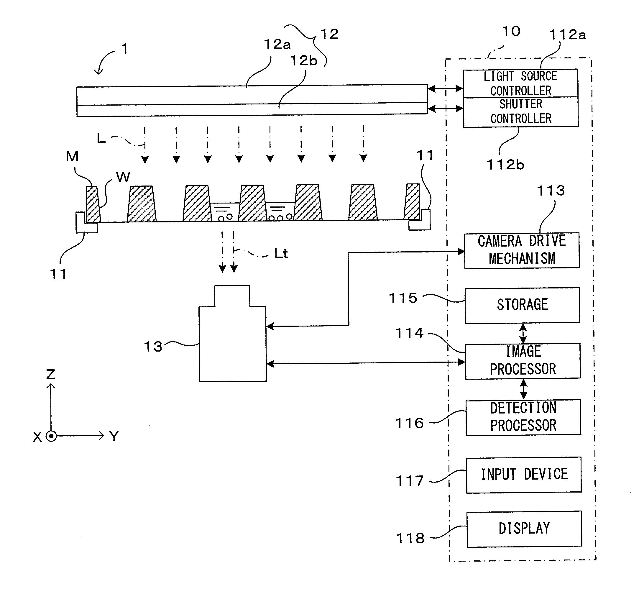
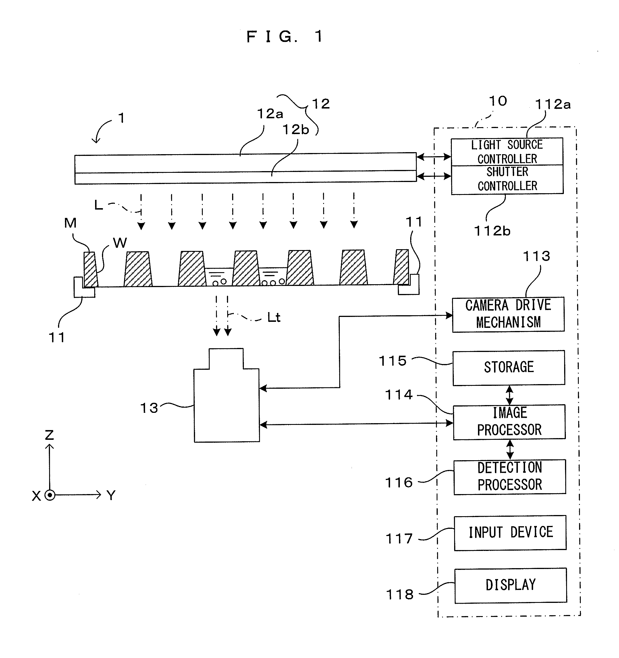
[0031]FIG. 1 is a diagram which shows a schematic configuration of an imaging apparatus according to this invention. This imaging apparatus 1 includes a holder 11 which holds a microplate M formed with a plurality of, e.g. 96 (12×8 matrix arrangement) wells W substantially in a horizontal state by coming into contact with a peripheral edge part of the lower surface of the microplate M, an illuminator 12 provided above the holder 11, an imaging unit 13 provided below the holder 11 and a controller 10 which performs a predetermined operation by governing these. Coordinate axes are set as shown in FIG. 1 for the following description. An X-Y plane is a horizontal plane and a Z-axis is a vertical axis.

[0032]The diameter and depth of each well W in the microplate M are typically about several millimeters. Fluid such as culture fluid, culture medium or reagent (only partly shown) is injected in each well W. Note that the number and size of the wells of the microplate as an object of this ...

second embodiment

[0064]FIGS. 6A to 6C are views which show a main part of the imaging apparatus according to this invention. As shown in FIG. 6A, a bar-like illuminator 22 for emitting light L21 toward the upper surface of the microplate M is provided above a microplate M held by a holder 11. Further, an imaging unit 13 includes the linear imaging device 133 shown in FIG. 3B and a longitudinal direction of the illuminator 22 is parallel to an arrangement direction of the light receiving elements in the linear imaging device 133. That is, this mode is a combination of an illuminator of one-dimensional pattern and an imaging device of one-dimensional pattern.

[0065]The illuminator 22 is moved to scan in a direction Ds relative to the microplate M integrally with the linear imaging device 133 in synchronization with a scanning movement of the linear imaging device 133 relative to the microplate M. Specifically, in this embodiment, a two-dimensional image is obtained by changing the position of the linea...

sixth embodiment

[0096]Further, in the sixth embodiment shown in FIG. 14B, an imaging unit 613 is arranged above a well W instead of arranging the imaging unit 13 below the well W as in the respective embodiments. More specifically, a half mirror 620 is provided above the well W and the imaging unit 613 is provided above the half mirror 620. Illumination light L61 emitted from an illuminator 62 including a light source 62a and a transmission light quantity adjuster 62b is caused to be incident on the half mirror 620 and reflected light L62 is caused to be incident on the well W. On the other hand, light L63 coming upward from the well W is incident on the imaging unit 613 through the half mirror 620. Even in such a case, substantially uniform light can be irradiated to an object in the well W and an image with little luminance nonuniformity can be obtained as in the above respective embodiments. Note that imaging is possible also when the illuminator 62, the half mirror 620 and the imaging unit 613 ...


PUM


Abstract

A preliminary image is obtained by irradiating illumination light, whose light quantity distribution is set at a standard state, to a specimen obtained by injecting fluid into a well from an illuminator capable of arbitrarily setting the light quantity distribution, for example, by a liquid crystal shutter, and a luminance distribution of the preliminary image is detected. As a result, luminance nonuniformity in the preliminary image is canceled by performing imaging with a light quantity distribution of illumination light to be incident on the well set such that an incident light amount is larger in a part with lower luminance.

Description

CROSS REFERENCE TO RELATED APPLICATION[0001]The disclosure of Japanese Patent Applications enumerated below including specifications, drawings and claims is incorporated herein by reference in its entirety:[0002]No. 2012-078846 filed on Mar. 30, 2012; and[0003]No. 2013-011736 filed on Jan. 25, 2013.BACKGROUND OF THE INVENTION[0004]1. Field of the Invention[0005]This invention relates to an imaging apparatus and an imaging method for imaging a specimen obtained by injecting fluid into a well and particularly to a technology for adjusting illumination light for illuminating the specimen in imaging.[0006]2. Description of the Related Art[0007]In medical or biological science experiments, cells or the like cultured in liquid or gel-like fluid injected into each well of a plate-like device in which a multitude of recesses called wells are arranged are, for example, observed and measured as a specimen. Such a device is, for example, called a microplate or a microtiter plate. In recent yea...

Claims


Application Information

Patent Timeline
Patent Type & Authority Applications(United States)
IPC IPC(8): H04N7/18
CPCH04N7/18G01N21/253G01N2201/067G01N2201/0631G01N2201/0634G01N21/255
Inventor FUJIMOTO, HIROKIKOBAYASHI, MASAYOSHIMIYAKE, TAKASHIMORIWAKI, SANZO
Owner DAINIPPON SCREEN MTG CO LTD
Why Eureka
Try Eureka