
Electric charge generating device

a technology of electric charge and generating device, which is applied in the direction of electrostatic charge, basic electric elements, corona discharge, etc., can solve the problems of increasing the potential amplitude of the target object and the source of noise at the obj

Active Publication Date: 2013-10-03
SMC CORP
View PDF4 Cites 10 Cited by
  • Summary
  • Abstract
  • Description
  • Claims
  • Application Information

AI Technical Summary

Benefits of technology

The patent text describes a way to generate positive and negative ions while minimizing induced charge and noise. This is done by adjusting the generation periods of the ions to make their arrival periods short. The text also mentions that the first and second extraction lines and supply lines are arranged in a way that can cancel each other out, which helps to reduce noise caused by the wiring arrangement. The technical effect of this invention is the ability to generate ions with less noise and greater control over their arrival times.

Problems solved by technology

Further, charge induced on the target object (hereinafter referred to as induced charge), which is caused by the power source that applies the AC high voltage to the needle electrodes, or by the wires that electrically connect the power source and the needle electrodes, becomes a source of noise at the object, and in this case as well, the potential amplitude at the target object increases.

Method used


Image

  • Electric charge generating device
  • Electric charge generating device
  • Electric charge generating device

Examples


Embodiment Construction

[0075]A preferred embodiment of an electric charge generating device according to the present invention will be described in detail below with reference to the accompanying drawings.

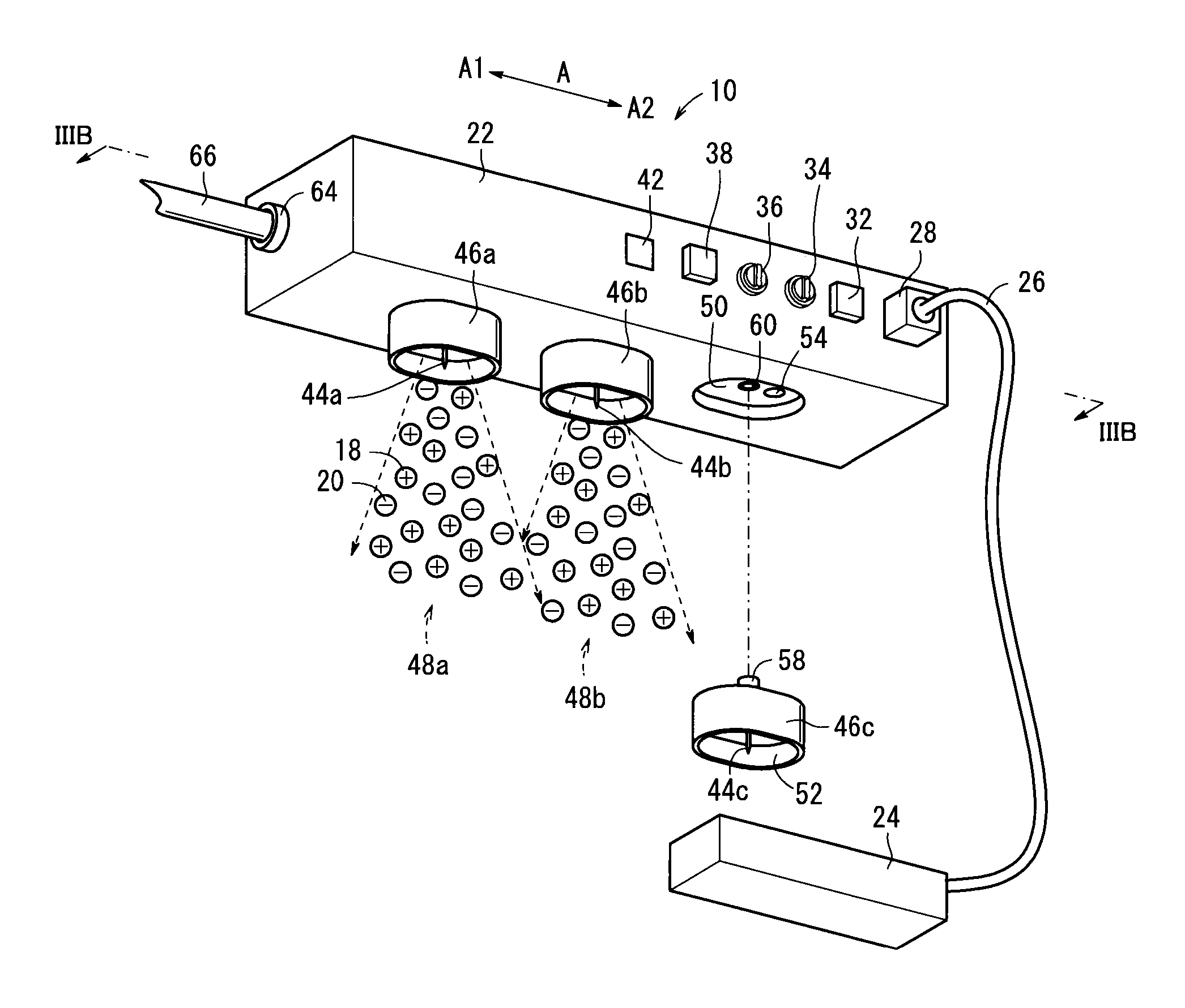
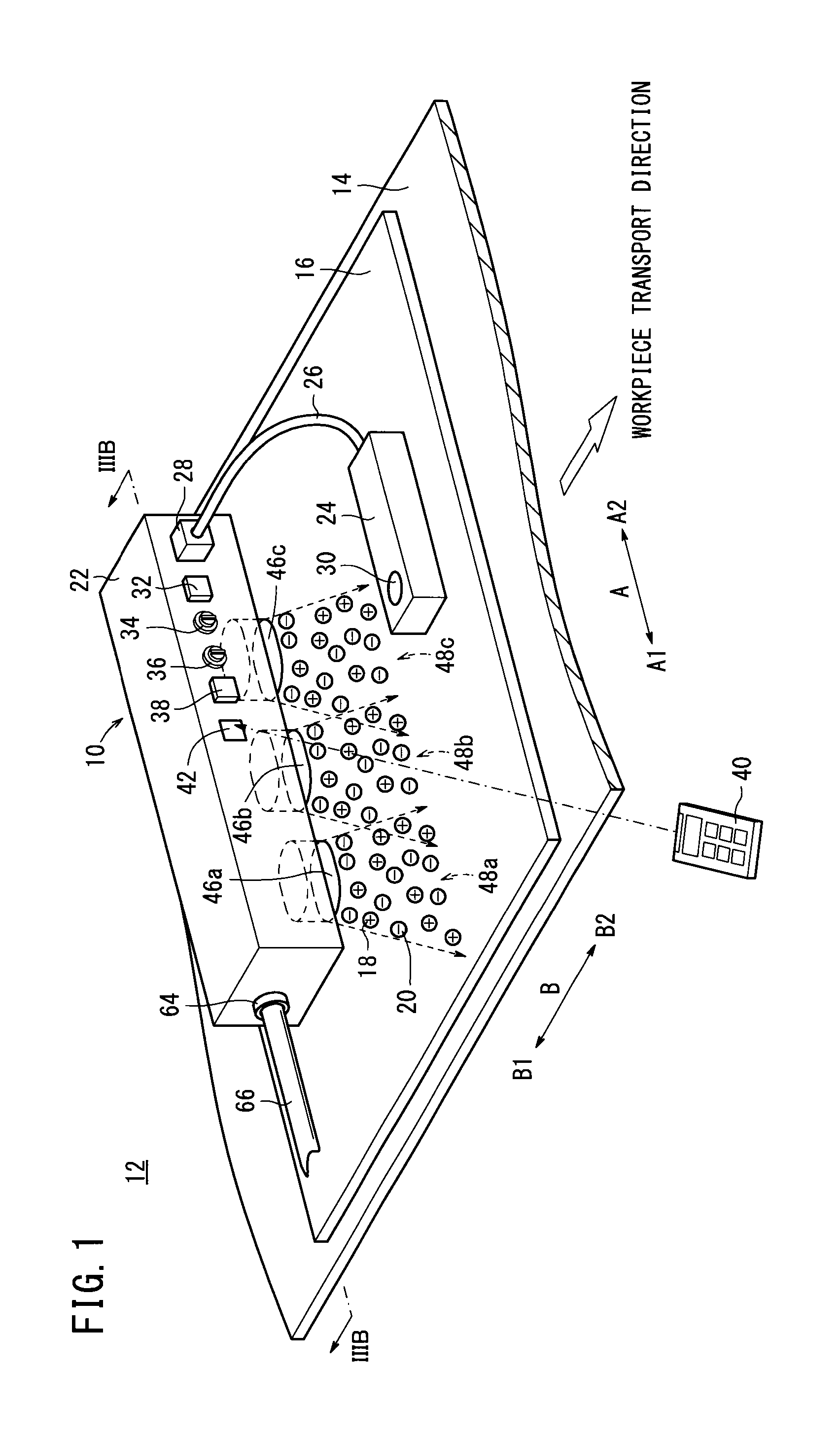
[0076]FIG. 1 is a perspective view of a charge removal system 12 equipped with an ionizer 10 serving as an electric charge generating device according to the present embodiment.

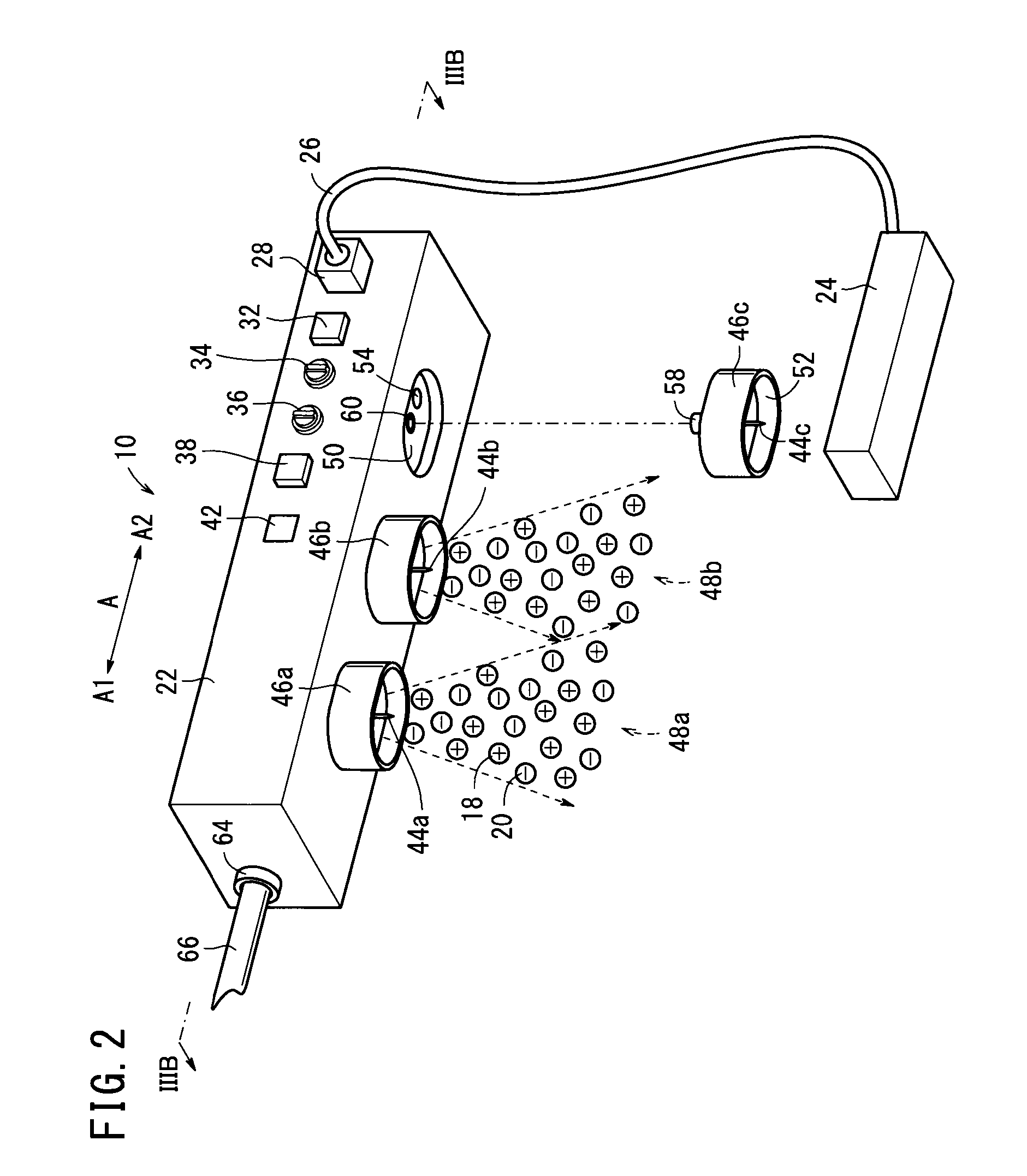
[0077]As shown in FIGS. 1 and 2, the charge removal system 12 releases positive ions 18 and negative ions 20 from the ionizer 10 with respect to a workpiece (target object) 16, which is a target object from which static charge is to be removed, and which is conveyed on a conveyor 14. Thus, the charge removal system 12 operates to neutralize positive or negative charges that charge the workpiece 16 and to remove the charges from the workpiece 16. The workpiece 16, for example, may be a film or a glass substrate. Accordingly, the charge removal system 12 is applicable for removing charge from the glass substrate or the film, which i...


PUM


Abstract

An ionizer that acts as an electric charge generating device includes a first high voltage power source and a second high voltage power source, which are disposed in confronting relation to each other, and a first wiring arrangement and a second wiring arrangement, which are disposed in confronting relation to each other. The first high voltage power source applies an AC high voltage to needle electrodes via the first wiring arrangement, whereas the second high voltage power source applies an AC high voltage, which is 180° out of phase with the aforementioned AC high voltage, to needle electrodes via the second wiring arrangement.

Description

CROSS-REFERENCE TO RELATED APPLICATION[0001]This application is based upon and claims the benefit of priority from Japanese Patent Application No. 2012-082674 filed on Mar. 30, 2012, the contents of which are incorporated herein by reference.BACKGROUND OF THE INVENTION[0002]1. Field of the Invention[0003]The present invention relates to an electric charge generating device for generating ions, and more specifically, relates to an electric charge generating device that operates favorably as an ionizer for neutralizing static charge on a charged object and removing static charge from the object by releasing ions toward the object as a target object to be neutralized.[0004]2. Description of the Related Art[0005]Known types of ionizers for neutralizing charge and removing static charge from a charged target object to be neutralized by releasing ions toward the target object are disclosed in U.S. Pat. No. 6,693,788 and International Publication No. WO 2007 / 122742, for example.[0006]In an...

Claims


Application Information

Patent Timeline
IPC IPC(8): H01T23/00
CPCH01T23/00H01T19/04
Inventor SUZUKI, SATOSHIORIHARA, MASAYUKI
Owner SMC CORP
Learn More