Connector mechanism for connecting a plug

a technology of connecting mechanism and plug, which is applied in the direction of network connection, coupling device connection, two-part coupling device, etc., can solve the problems of increasing manufacturing cost, bringing more challenges to mechanical design, and shafts that may be easily broken by shearing, etc., to achieve low manufacturing cost, easy assembly, and low manufacturing cost

Active Publication Date: 2013-10-03
WISTRON CORP
View PDF10 Cites 25 Cited by
  • Summary
  • Abstract
  • Description
  • Claims
  • Application Information

AI Technical Summary

Benefits of technology

[0020]The present invention provides the connector mechanism with the rotary cover driven by the resilient plate for fastening the plug. The resilient plate drives the rotary cover to rotate by deflection deformation. The stopping portion for fastening the plug is disposed on the resilient plate, instead of being disposed on the rotary cover. Therefore, the fixing structure for fixing the plug does not have to be replaced as the rotary cover is replaced for mechanical design of the notebook computer with different types, so that manufacture cost is not increased. Thus, the connector mechanism of the present invention has advantages of satisfying the height specification, low manufacture cost, enough assembly strength as well as keeping the aesthetic feeling of appearance.

Problems solved by technology

However, because of the thinning size of the notebook computer, it brings more challenges for mechanical design.
However, it utilizes a spring sheathed on a shaft of the rotary cover to rotate the rotary cover, so that the shaft may be broken easily by shearing force.
Furthermore, the fixing structure for fixing a connector is disposed on the rotary cover, so the fixing structure has to be replaced as the rotary cover is replaced for mechanical design of the notebook computer with different types, resulting in increase of manufacture cost.
Thus, the conventional connector mechanism has importance issues of satisfying the height specification, low manufacture cost, enough assembly strength as well as keeping the aesthetic feeling of appearance.

Method used


Image

  • Connector mechanism for connecting a plug
  • Connector mechanism for connecting a plug
  • Connector mechanism for connecting a plug

Examples


Embodiment Construction

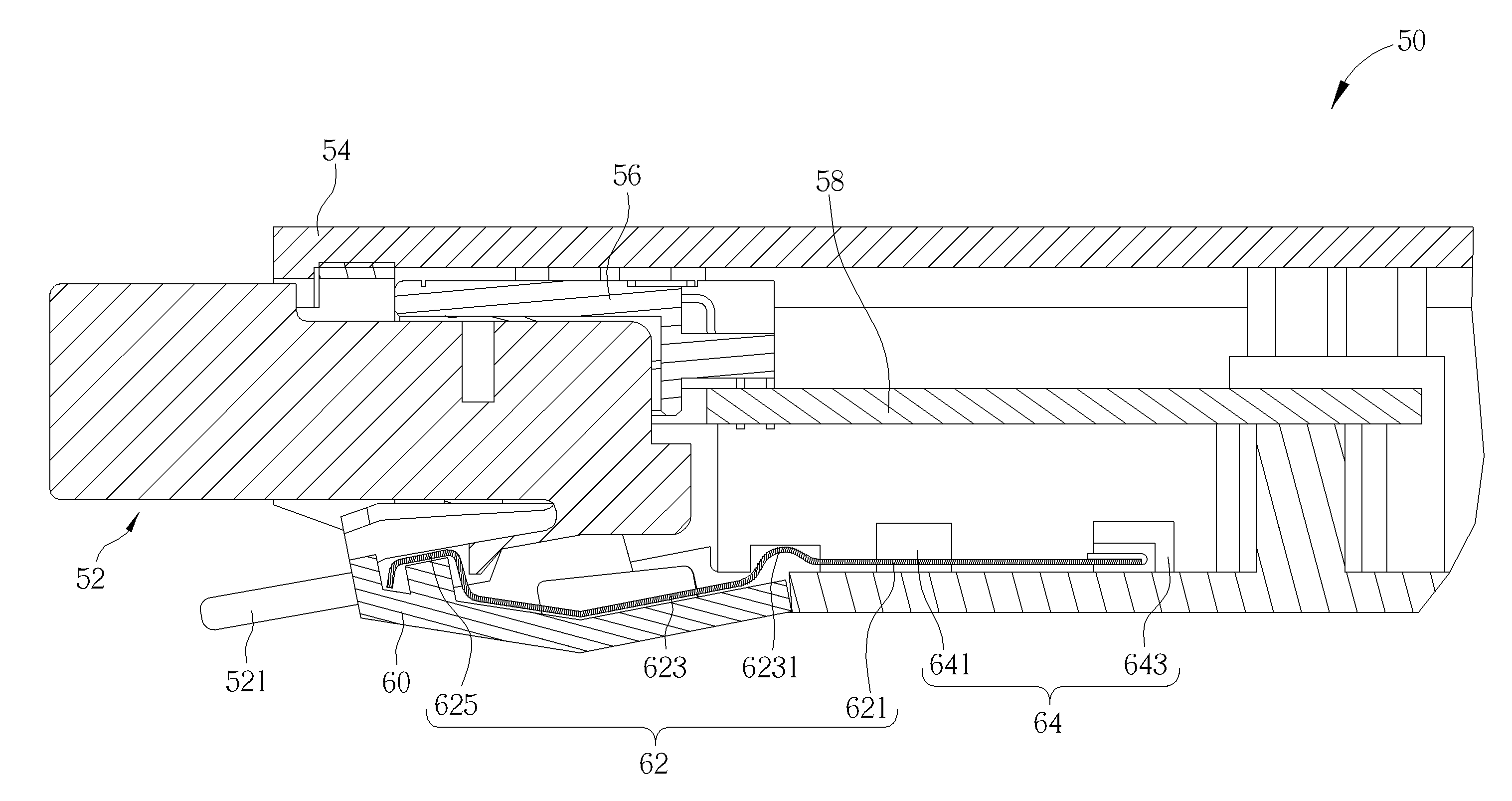
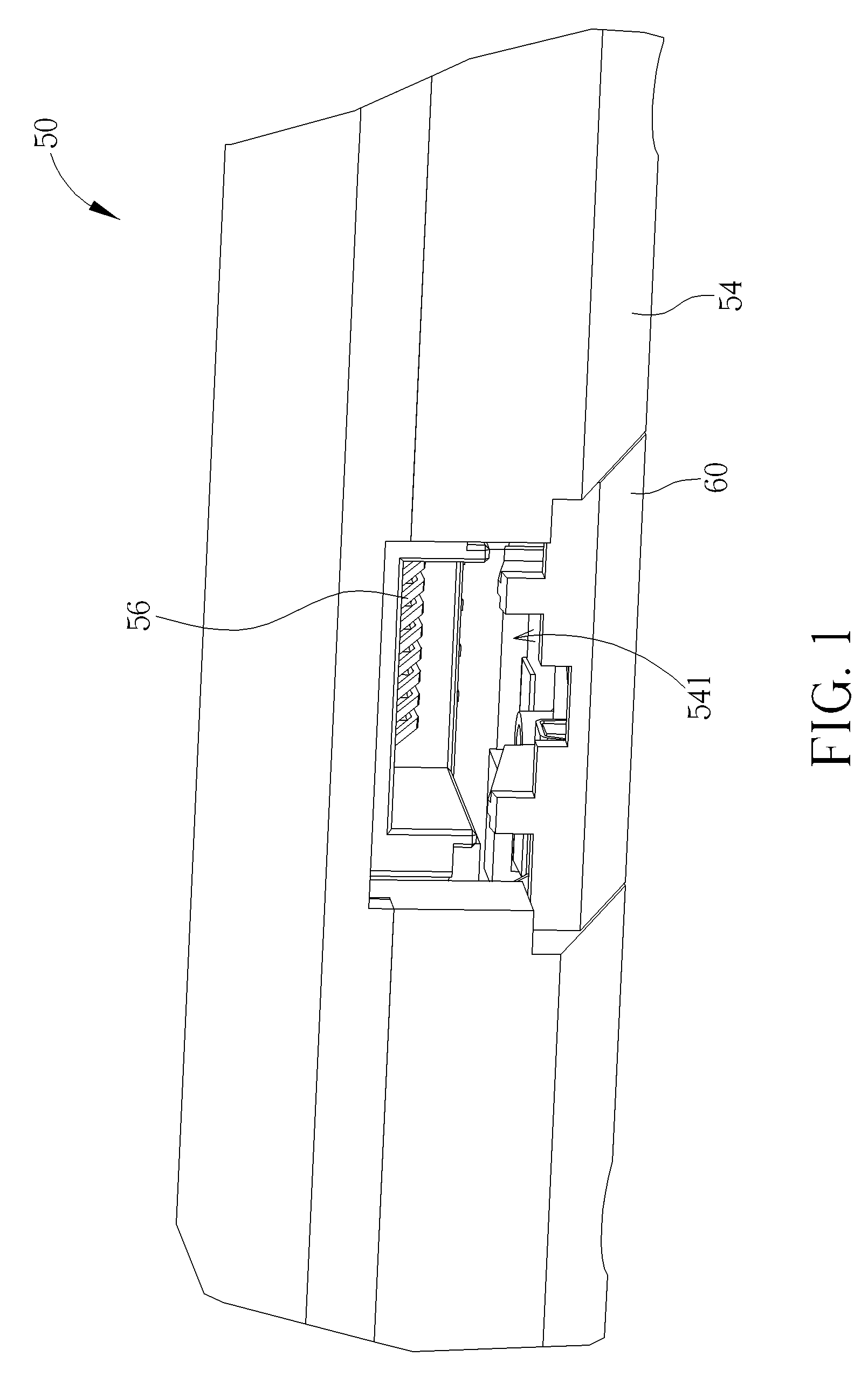
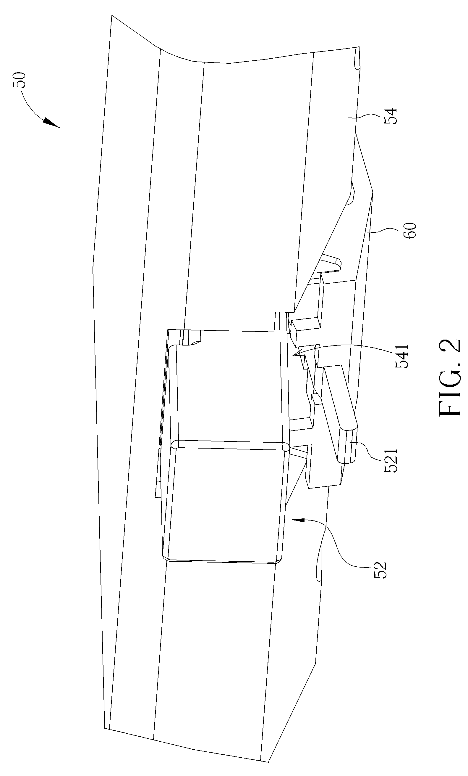
[0027]Please refer to FIG. 1 to FIG. 4. FIG. 1 is a schematic drawing of a connector mechanism 50 according to an embodiment of the present invention. FIG. 2 is a schematic drawing of a plug 52 inserting into the connector mechanism 50 according to the embodiment of the present invention. FIG. 3 is an internal structural diagram of the connector mechanism 50 according to the embodiment of the present invention. FIG. 4 is an exploded diagram of the connector mechanism 50 according to the embodiment of the present invention. The connector mechanism 50 can be disposed on a lateral side of a notebook component. The connector mechanism 50 includes a casing 54 whereon an opening 541 is formed. The casing 54 can be an external housing of the notebook computer. The connector mechanism 50 further includes a socket 56 installed inside the casing 54 and disposed on a side of the opening 541. The socket 56 can be a half socket and installed on a circuit board 58. The socket 56 can be an Etherne...


PUM


Abstract

A connector mechanism includes a casing, a socket, a rotary cover and a resilient plate. An opening is formed on the casing. The resilient plate is connected to an inner side of the casing and the rotary cover for driving the rotary cover to rotate relative to the casing. The resilient plate includes a fixing portion fixed on the inner side of the casing, a driving portion resiliently connected to the fixing portion and the rotary cover for driving the rotary cover to rotate relative to the casing by deflection relative to the fixing portion, and a stopping portion disposed on the driving portion for stopping a tongue of a plug as the plug passes through the opening to connect with the socket, so as to fasten the plug.

Description

BACKGROUND OF THE INVENTION[0001]1. Field of the Invention[0002]The present invention relates to a connector mechanism for connecting a plug, and more particularly, to a connector mechanism with a rotary cover driven by a resilient plate for fastening a plug.[0003]2. Description of the Prior Art[0004]With the development of information and computer technology, the size of a computer is becoming smaller and the computer is utilized in a wide variety of fields. In order to expand functions of a computer system for satisfying a user's various demands, various external devices of the computer system come with the trend. For example, an external hard disk drive and a portable storage device can expand the memory capacity of the computer system. An external optical disk drive and an optical disk writer can expand multimedia access function of the computer system. A network cable allows the computer system to be connected to an internet so as to gather information online or surf webpage. H...

Claims


Application Information

Patent Timeline
Patent Type & Authority Applications(United States)
IPC IPC(8): H01R13/627
CPCH01R13/627H01R13/447H01R2201/06H01R24/64H01R2201/04H01R13/6272
Inventor KUO, WEI-CHINGLAI, TING-FANGCHIU, CHUAN-HSIAO
Owner WISTRON CORP
Why Eureka
Try Eureka