Bowling ball elevating assembly for an automatic pinsetter

a technology of automatic pinsetters and elevating parts, which is applied in the field of improved bowling ball elevating parts for automatic pinsetters, can solve problems such as damage to bowling balls

Inactive Publication Date: 2013-10-03
KEGEL LLC
View PDF0 Cites 2 Cited by
  • Summary
  • Abstract
  • Description
  • Claims
  • Application Information

AI Technical Summary

Benefits of technology

[0010]It is a goal of the present invention to provide an improvement to an existing automatic pinsetting device by changing the position of the ball lift drive belt pulleys. It

Problems solved by technology

It has been learned that in the current pinsetter the bowling ball may be damaged by either a drive belt pulley which is made of steel or by jammed

Method used


Image

  • Bowling ball elevating assembly for an automatic pinsetter
  • Bowling ball elevating assembly for an automatic pinsetter
  • Bowling ball elevating assembly for an automatic pinsetter

Examples


Embodiment Construction

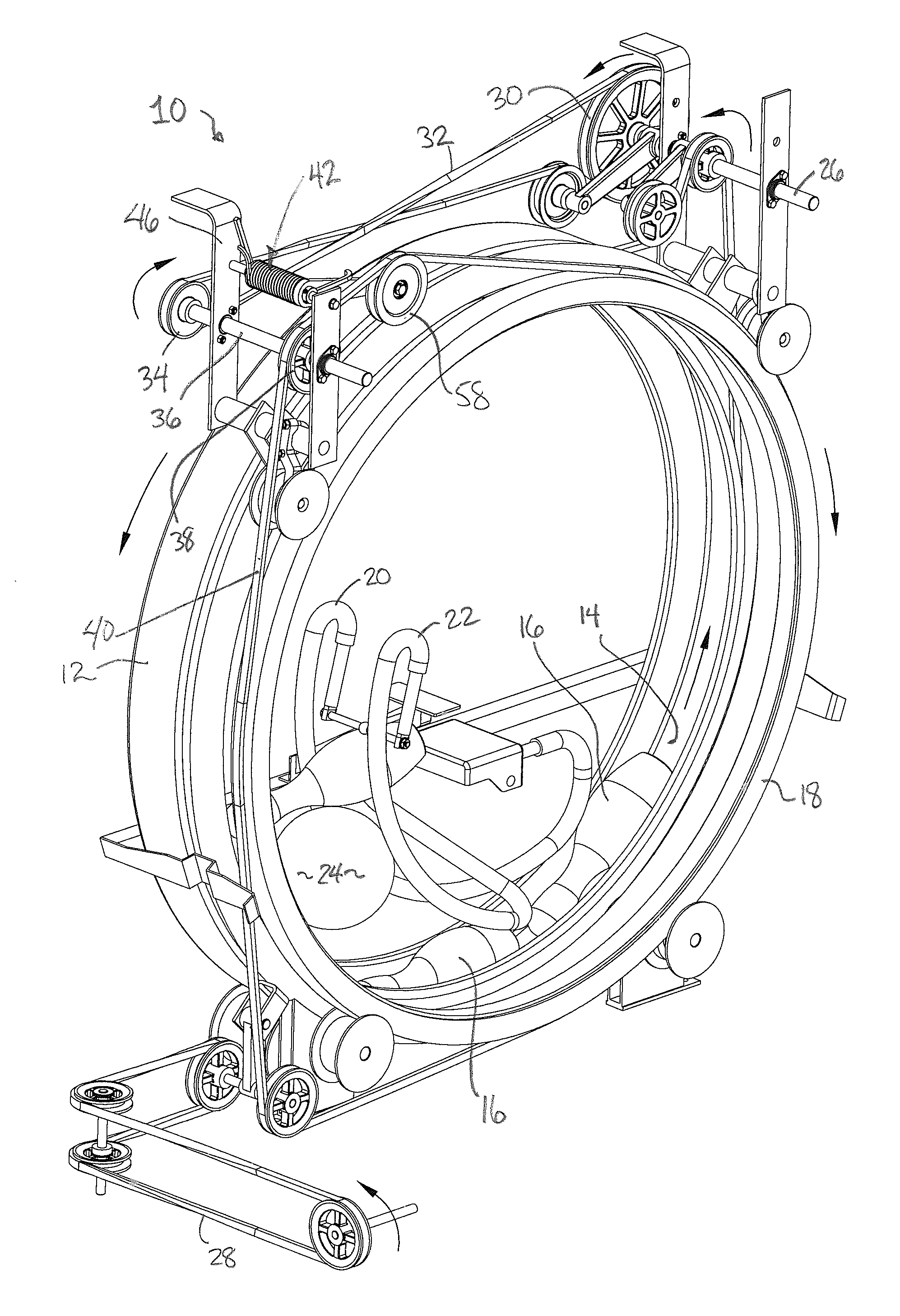
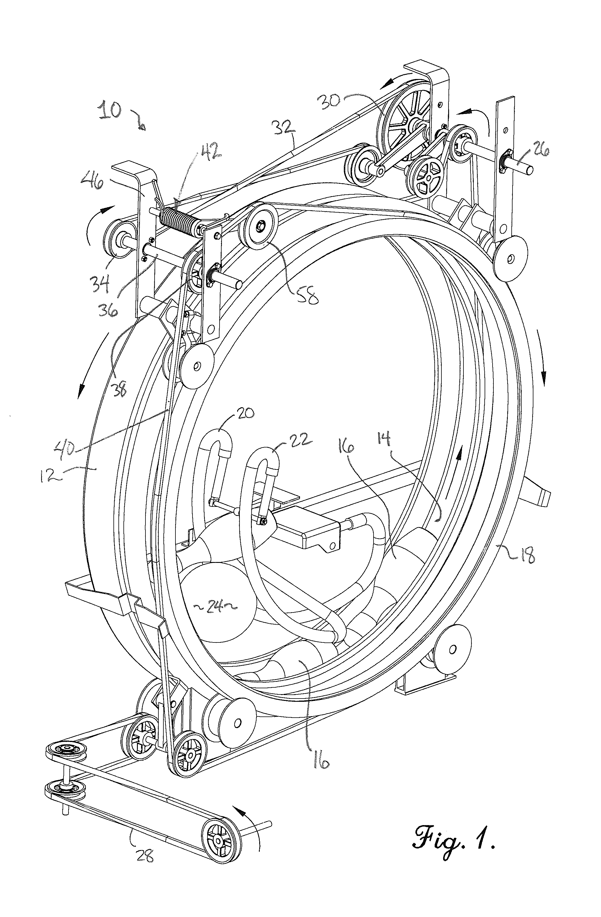
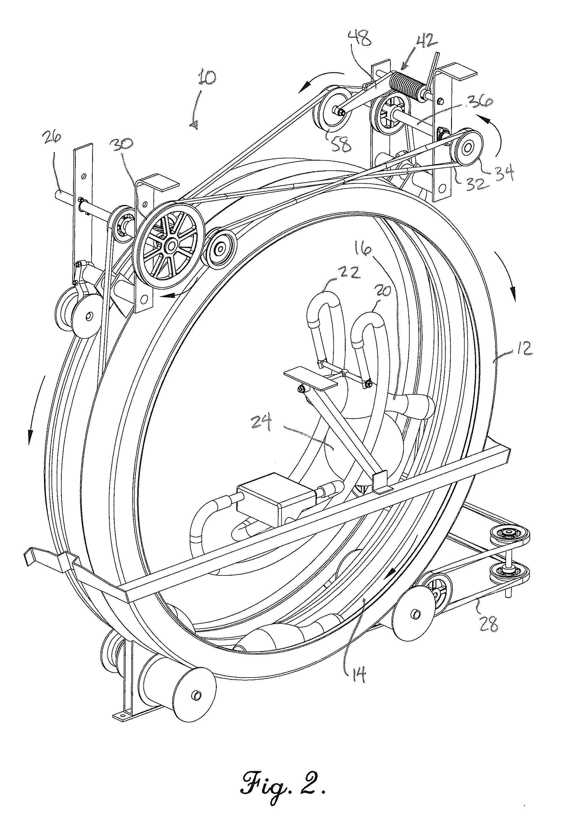
[0026]Referring now to the drawings, FIGS. 1, 2 and 3 show a portion of an automatic pinsetter 10, more particularly parts of the ball and pin elevating mechanisms. The pin elevating mechanism includes a pin elevating ring member 12 which includes pin-receiving pockets 14 configured for elevating bowling pins 16 upwardly for deposit onto a turnaround pan (not shown) which receives the pins 16 and orients them for delivery via a cross-conveyor to a turret. The ball elevating mechanism includes a ball elevating ring member 18 and a pair of ball lift rods 20 and 22. A bowling ball 24 delivered by the bowler is received in a pit at the rear of the pin deck and then travels to the ball elevating ring member 18. The pin elevating ring member 12 and the ball elevating ring member 18 are constantly rotating, but in opposite directions as shown by the arrows in FIGS. 1, 2 and 3. Typically, a single electric motor (not shown) is operatively coupled to a cross shaft 26 for driving both the pin...


PUM


Abstract

A bowling ball elevating assembly for an automatic pinsetter includes an idler pulley assembly having an idler arm and a tension spring causing the idler arm to maintain tension on a ball wheel belt driving a ball elevating ring member. An adjustment arm and a tension arm are mounted to an idler pulley shaft enabling adjusting the amount of tension applied by the tension spring to the idler arm, and consequently the tensioning force applied by an idler pulley to the ball wheel belt, thereby permitting slippage of the ball wheel belt relative to the ball elevating ring member when bowling pins and a bowling ball become jammed in the pinsetter. An improved idler v-pulley wheel has a reduced frictional engagement with the ball wheel belt, and improved positioning of the ball lift drive belt pulley reduces stress on the ball wheel belt.

Description

[0001]This application claims the benefit of U.S. Provisional Patent Application No. 61 / 618,460 filed Mar. 30, 2012, the entire disclosure of which is incorporated herein by reference.BACKGROUND OF THE INVENTION[0002]1. Field of the Invention[0003]The present invention concerns an improved bowling ball elevating assembly for automatic pinsetters. More particularly, it is concerned with a bowling ball elevating assembly including a ball wheel drivebelt assembly having a modified idler arm and pulley which permits slippage of the elevating drive to reduce or avoid damage to bowling balls when a bowling pin and bowling ball are jammed together in the pinsetter.[0004]2. Description of the Prior Art[0005]Automatic pinsetters are well known mechanisms which have drastically reduced labor in bowling centers by avoiding the necessity of human pinsetters. These automated pinsetters perform a variety of functions including sweeping pins from the pin deck, positioning pins for play, and return...

Claims


Application Information

Patent Timeline
IPC IPC(8): A63D1/00
CPCA63D1/00A63D5/08A63D5/02
Inventor BASHAK, CHUCK
Owner KEGEL LLC
Why Eureka
Try Eureka