Automatic transmission

a transmission and automatic technology, applied in mechanical equipment, transportation and packaging, gear shifting, etc., can solve the problems of difficult to increase the gear spread, and low fuel economy, and achieve the effect of low cos

Inactive Publication Date: 2013-10-03
AISIN AW CO LTD
View PDF6 Cites 4 Cited by
  • Summary
  • Abstract
  • Description
  • Claims
  • Application Information

AI Technical Summary

Benefits of technology

[0020]Thus, since the first clutch, the third clutch, and the first brake may be placed on the axially opposite side of the output member from the planetary gear set, the first clutch, the third clutch, and the first brake can be arranged in a compact manner without causing interference between the members. Moreover, the structure on the axially opposite side of the output...

Problems solved by technology

One method to further increase the number of shift speeds from that of the automatic transmission of JP 2000-220704 A or JP 2006-161927 A is to merely add a planetary gear, but this may hinder downsizing and weight reduction.
However, in the case where the planetary gear set is used in the manner described in JP 2006-161927 A, it is difficult to increase the gear spread...

Method used


Image

  • Automatic transmission
  • Automatic transmission
  • Automatic transmission

Examples


first embodiment

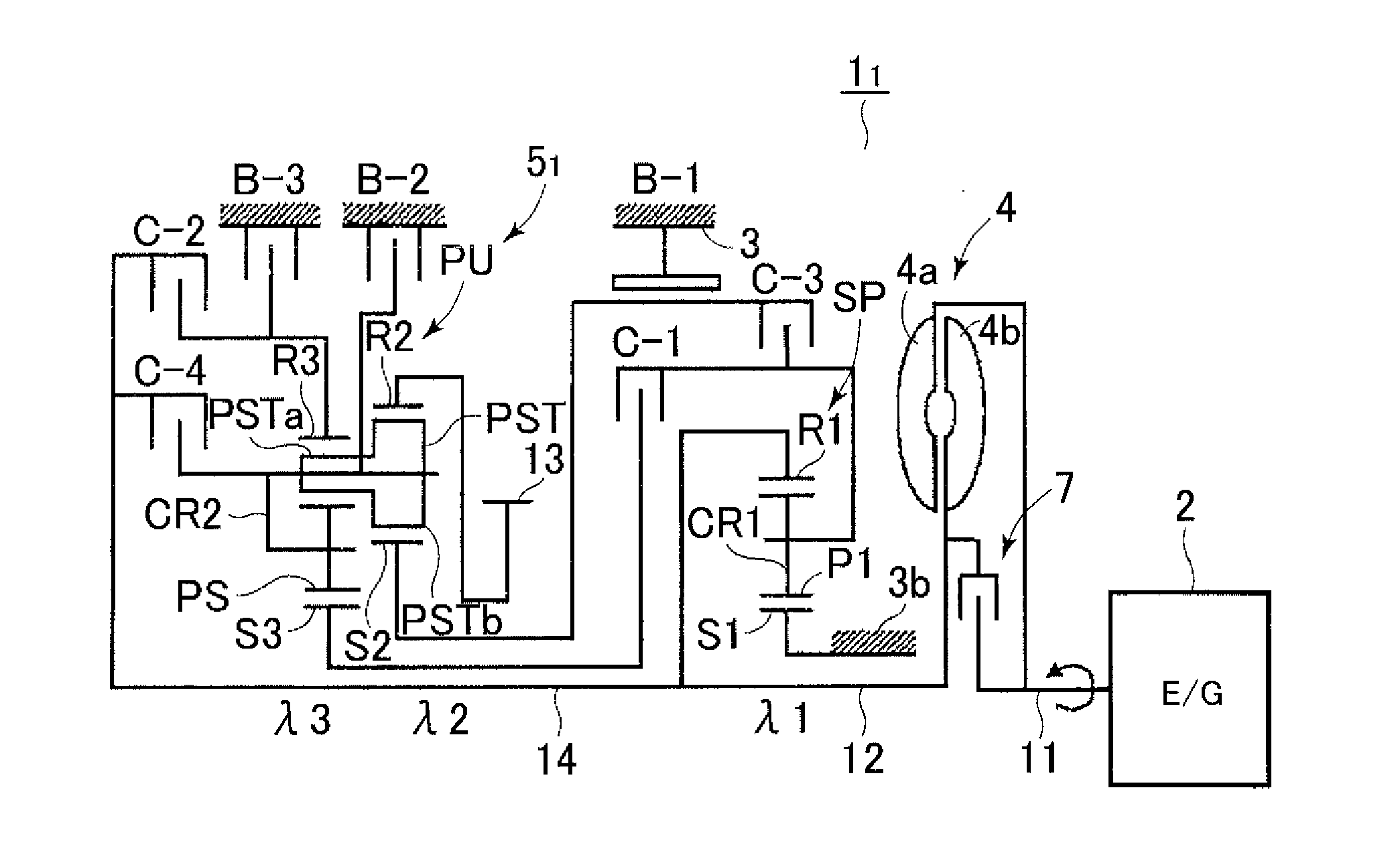
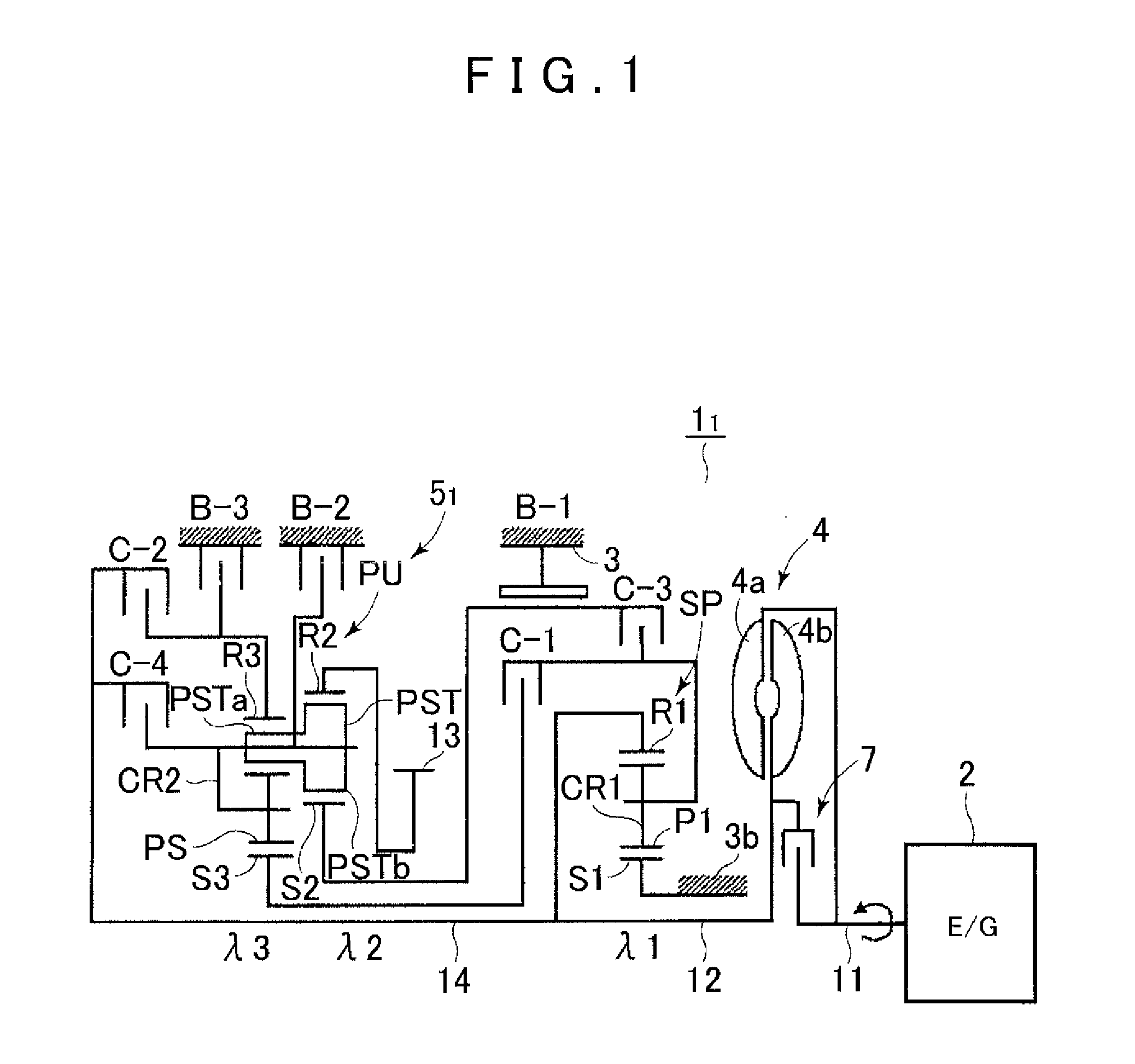
[0029]A first embodiment of the present invention will be described below with reference to FIGS. 1 to 4. First, the general configuration of an automatic transmission 11 to which the present invention can be applied will be described with reference to FIG. 1. As shown in FIG. 1, the automatic transmission 11 that is preferably used for, for example, front-engine, front-drive (FF) type vehicles has an input shaft 11 of the automatic transmission 11 which can be connected to an engine (drive source) 2, and includes a torque converter 4 and a speed change mechanism 51 which are disposed about the axial direction of the input shaft 11.

[0030]In the automatic transmission 11 that is described below and is preferably mounted on an FF type vehicle, the lateral direction in the figures actually corresponds to the lateral direction of the vehicle, and as used herein, the “front side” refers to the engine 2 side of a power transmission path in the axial direction, and the “rear side” refers t...

second embodiment

[0084]A second embodiment in which the first embodiment is partially modified will be described with reference to FIGS. 5 to 8. In the second embodiment, portions similar to those of the automatic transmission 11 according to the first embodiment will be denoted by the same reference characters, and description thereof will be omitted.

[0085]An automatic transmission 12 according to the second embodiment is different from the first embodiment in that the planetary gear SP outputting the decelerated rotation shown in FIGS. 1 and 4 is replaced with a double pinion planetary gear shown in FIGS. 5 and 8. Specifically, in a planetary gear DP, a first carrier CR1 has a first pinion P1 meshing with a first sun gear S1, and a second pinion P2 meshing with the first pinion P1 and a first ring gear R1, and rotatably supports the first pinion P1 and the second pinion P2.

[0086]As shown in FIGS. 5 and 8, this planetary gear SP is configured so that the first sun gear S1 is fixed to a boss portion...


PUM


Abstract

An automatic transmission is configured to achieve at least ten forward speeds and one reverse speeds. This is achieved through the use of two planetary gear sets with a plurality of clutches and brakes configured to operably couple different components of the two planetary gears to achieve different speeds. For example, operation of a first clutch inputs decelerated rotation of a reduction planetary gear to a third sun gear. Operation of a second clutch transmits from an input shaft to a third ring gear, a third clutch inputs decelerated rotation of the reduction planetary gear to the second sun gear, a fourth clutch transmits from the input shaft to the second carrier, a first brake prevents a second sun gear from rotating, a second brake prevents a carrier from rotating, a third brake capable prevents a third ring gear from rotating.

Description

INCORPORATION BY REFERENCE[0001]The disclosure of Japanese Patent Application No. 2012-074915 filed on Mar. 28, 2012 including the specification, drawings and abstract is incorporated herein by reference in its entirety.BACKGROUND OF THE INVENTION[0002]The present invention relates to automatic transmissions that are mounted on, for example, vehicles etc., and more particularly to automatic transmissions that include a reduction planetary gear capable of outputting decelerated rotation and a planetary gear set achieving multi-speed shifting based on decelerated rotation and input rotation.DESCRIPTION OF THE RELATED ART[0003]In recent years, the number of shift speeds of stepped automatic transmissions that are mounted on vehicles has been increased in order to improve fuel economy of the vehicles. Stepped automatic transmissions that include a reduction planetary gear capable of outputting decelerated rotation and a planetary gear set achieving multi-speed shifting based on decelera...

Claims


Application Information

Patent Timeline
IPC IPC(8): F16H3/62
CPCF16H3/62F16H3/66F16H2200/2048F16H2200/2007F16H2200/2025F16H2200/0069F16H2200/201F16H2200/2056
Inventor ANDO, MASAHIKOSUGIURA, NOBUTADASUZUKI, HAYATO
Owner AISIN AW CO LTD
Why Eureka
Try Eureka